

Device and Method for Lighting
- Summary
- Abstract
- Description
- Claims
- Application Information
AI Technical Summary
Benefits of technology
Problems solved by technology
Method used
Image

Examples
Embodiment Construction
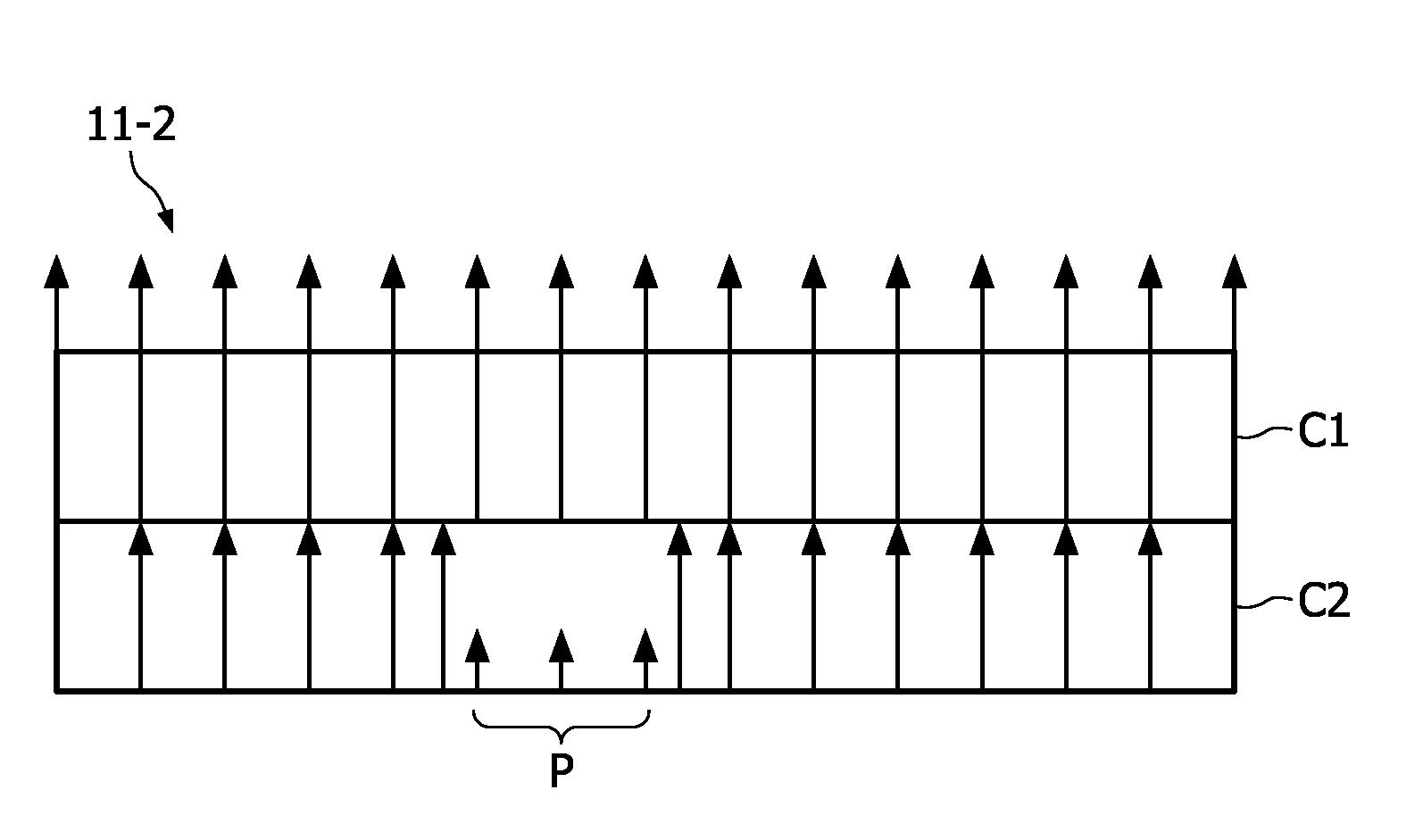
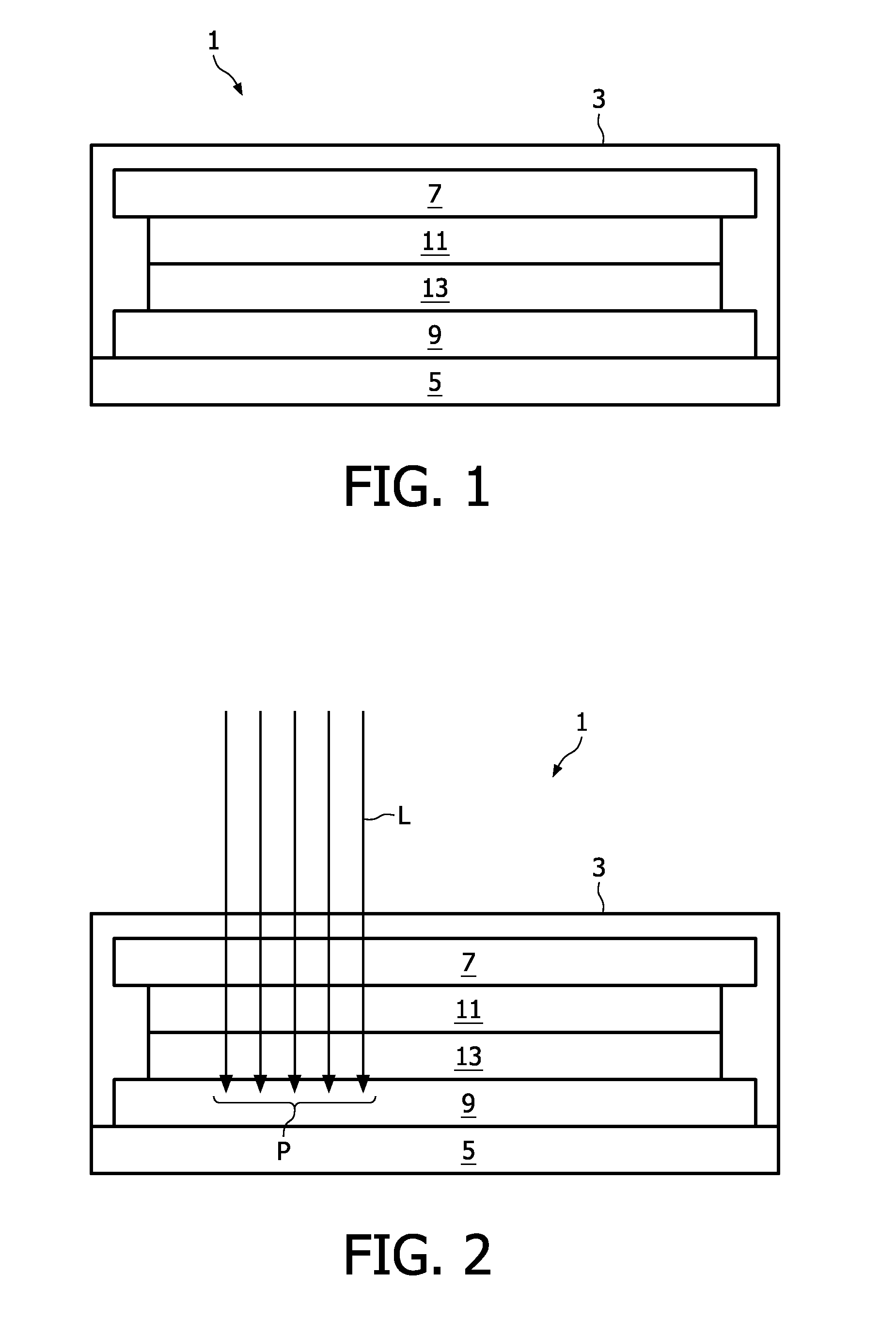
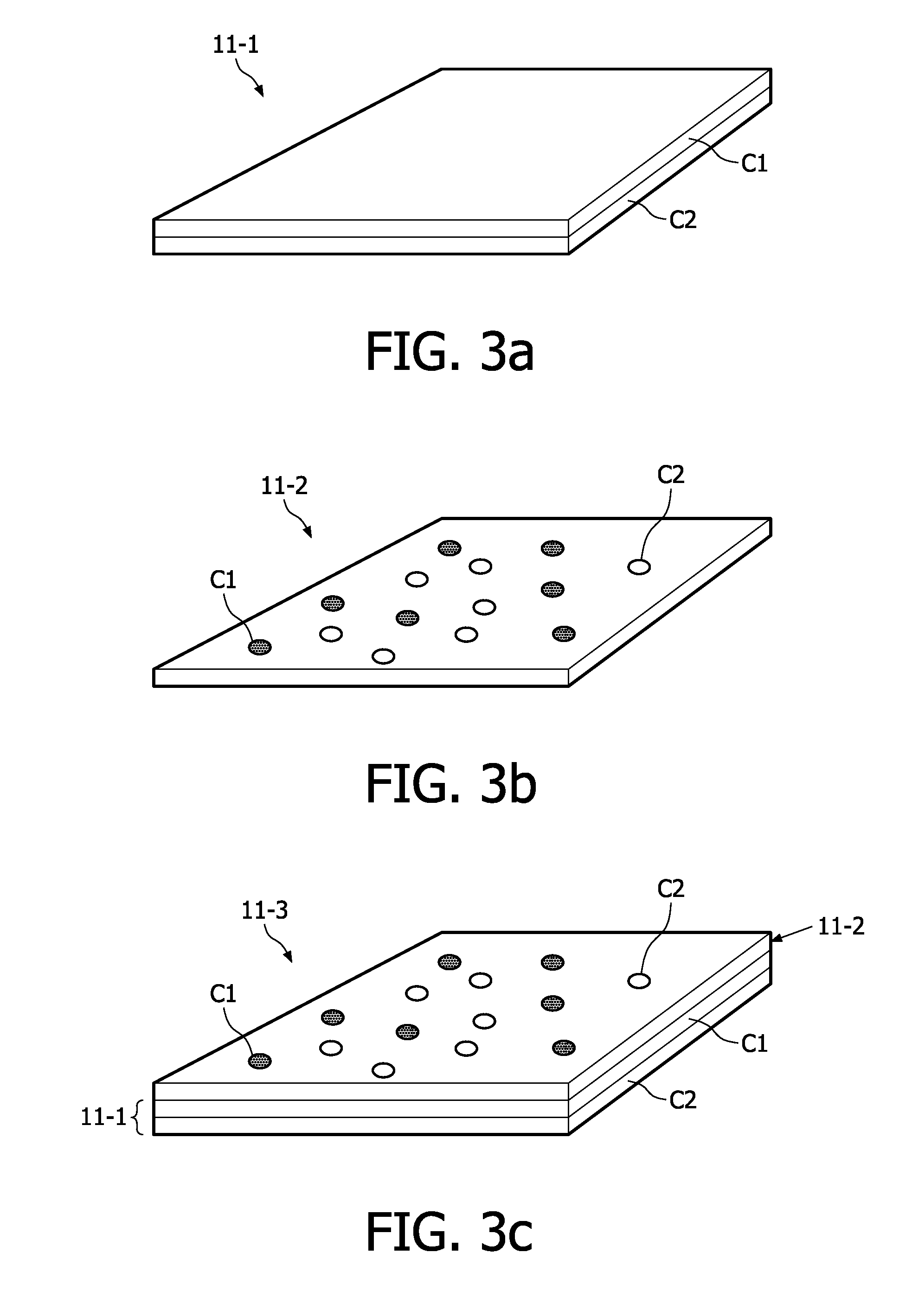
[0039]FIG. 1 shows a cross-sectional view of an embodiment of an OLED device 1 according to the inventive concept. The OLED device 1 comprises an encapsulating body 3, made of e.g. glass, metal or other hermetic coatings for the protection of internal components 7,9,11,13 from contamination, e.g. moisture or dirt. The encapsulating body 3 might also contain getters to absorb water which might have penetrated the encapsulation. Inside the encapsulating body 3, the OLED device comprises a cathode 7, an anode 9 and a light emitting layer comprising an emissive layer 11 and an electrically conductive layer 13. These internal components may be placed on a substrate 5 made of e.g. glass, by e.g. placing the anode 9, the conductive layer 13, the emissive layer 11, and the cathode 7 on the substrate 5 in the mentioned order. The emissive and conductive layers 11 and 13, respectively, may be produced from an organic material such as a polymer or oligomer. The emissive layer 11 can comprise d...
PUM
 Abstract
Description
Claims
Application Information