Method and apparatus of transmitting information in wireless communication system

Active Publication Date: 2011-07-14
LG ELECTRONICS INC
94 Cites 96 Cited by

AI-Extracted Technical Summary

Problems solved by technology

However, a wireless channel has an abnormal characteristic such as path loss, noise, fading due to multipath, an inter-symbol interference (ISI), the Doppler effect due to mobility of a user equipment, etc.
In this respect, however, combining of the information transmission method based on the CDM scheme to a MIMO tec...

Benefits of technology

[0023]A method and an apparatus of effectively transmitting information...

Abstract

A method and an apparatus of transmitting information in a wireless communication system are provided. The method includes transmitting information based on a first resource index through a first antenna and transmitting the information based on a second resource index through a second antenna.

Application Domain

Technology Topic

Image

  • Method and apparatus of transmitting information in wireless communication system
  • Method and apparatus of transmitting information in wireless communication system
  • Method and apparatus of transmitting information in wireless communication system

Examples

  • Experimental program(4)

Example

1. First Exemplary Embodiment
[0206]In the first exemplary embodiment, a Walsh-Hadamard matrix is used as the OS.
[0207]The following equation represents a 4×4 Walsh-Hadamard matrix:
MathFigure 14 [ 1 1 1 1 1 - 1 1 - 1 1 1 - 1 - 1 1 - 1 - 1 1 ] [ Math . 14 ]
[0208]Each of the four rows of the Walsh-Hadamard matrix constitutes OSs in which they are mutually orthogonal. Namely, four OSs such as [1, 1, 1, 1], [1, −1, 1, −1], [1, 1, −1, −1], and [1, −1, −1, 1] may be defined. In the 3GPP LTE, the three OSs excluding [1, −1, −1, 1] are used (See Table 3), but [1, −1, −1, 1] can be also used as the OS.
[0209]The case where R=2, a first OS is [1, −1, 1, −1], and a second OS is [1, 1, −1, −1] will now be taken as an example.
[0210]The first spread sequence becomes [d(0), −d(0), d(0), −d(0)], the second spread sequence becomes [d(0), d(0), −d(0), −d(0)]. If reception signal is y=[y(0), y(1), y(2), y(3)], the reception signal may be represented by the following equation.
MathFigure 15
y(0)=d(0)h1+d(0)h2+n(0)
y(1)=−d(0)h1+d(0)h2+n(1)
y(2)=d(0)h1−d(0)h2+n(2)
y(3)=−d(0)h1−d(0)h2+n(3)   [Math.15]
[0211]If a first estimated symbol obtained by despreading the first OS [1, −1, 1, −1] from the reception signal is d′1(0) and a second estimated symbol obtained by despreading the second OS [1, 1, −1, −1] from the reception signal is d′2(0), the first and second estimated symbols may be represented by the following equation.
MathFigure 16
d′1(0)=4d(0)h1+n′1
d′2(0)=4d(0)h2+n′2 [Math.16]
[0212]An estimated symbol d′(0) obtained by combining the first and second estimated symbols may be represented by the following equation.
MathFigure 17 d ′ ( 0 ) = d 1 ′ ( 0 ) h 1 * + d 2 ′ ( 0 ) h 2 * = ( 4 d ( 0 ) h 1 + n 1 ′ ) h 1 * + ( 4 d ( 0 ) h 2 + n 2 ′ ) h 2 * = 4 ( h 1 2 + h 2 2 ) d ( 0 ) + n ′ [ Math . 17 ]
[0213]In this manner, a diversity gain is obtained.

Example

2. Second Exemplary Embodiment
[0214]In the second exemplary embodiment, a discrete Fourier transform (DFT) code is used as an OS. The use of the DFT code is equivalent to a cyclic shift of another domain. Namely, the use of the DFT code in the time domain is equivalent to the cyclic shift in the frequency domain. Otherwise, the use of the DFT code in the frequency domain is equivalent to the cyclic shift in the time domain.
[0215]The following equation represents a 4×4 DFT code matrix.
MathFigure 18 [ 1 j2π · 1 · 0 / 4 j2π · 2 · 0 / 4 j2π · 3 · 0 / 4 1 j2π · 1 · 1 / 4 j2π · 2 · 1 / 4 j2π · 3 · 1 / 4 1 j2π · 1 · 2 / 4 j2π · 2 · 2 / 4 j2π · 3 · 2 / 4 1 j2π · 1 · 3 / 4 j2π · 2 · 3 / 4 j2π · 3 · 3 / 4 ] [ Math . 18 ]
[0216]Each of the four rows of the DFT code matrix constitutes OSs in which they are mutually orthogonal. Namely, four OSs having a length of 4 may be defined from the DFT code matrix.
[0217]The case where R=2, a first OS is w1, and a second OS is w2 as represented by the following equation will be taken as an example.
MathFigure 19
w1=[1, ej2π·1·1/4, ej2π·2·1/4, ej2π·3·1/4]
w2=[1, ej2π·1·2/4, ej2π·2·2/4, ej2π·3·2/4]  [Math.19]
[0218]A first spread sequence z1 and a second spread sequence z2 may be represented by the following equation.
MathFigure 20
z1=[d(0), d(0)ej2π·1·1/4, d(0)ej2π·2·1/4, d(0)ej2π·3·1/4]
z2=[d(0), d(0)ej2π·1·2/4, d(0)ej2π·2·2/4, d(0)ej2π·3·2/4]  [Math.20]
[0219]If a first estimated symbol obtained by despreading the first OS w1 from the reception signal is d′1(0) and a second estimated symbol obtained by despreading the second OS w2 from the reception signal is d′2(0), the first and second estimated symbols may be represented by the following equation.
MathFigure 21
d′1(0)=4d(0)h1+n′1
d′2(0)=4d(0)h2+n′2 [Math.21]
[0220]An estimated symbol d’(0) obtained by combining the first and second estimated symbols may be represented by the following equation.
MathFigure 22 d ′ ( 0 ) = d 1 ′ ( 0 ) h 1 * + d 2 ′ ( 0 ) h 2 * = ( 4 d ( 0 ) h 1 + n 1 ′ ) h 1 * + ( 4 d ( 0 ) h 2 + n 2 ′ ) h 2 * = 4 ( h 1 2 + h 2 2 ) d ( 0 ) + n ′ [ Math . 22 ]
[0221]In this manner, a diversity gain is obtained.

Example

3. Third Exemplary Embodiment
[0222]In the third exemplary embodiment, a resource used for information transmission includes an OS and the amount of CS. In this case, a resource index indicates an OS index and a CS index.
[0223]The rth spread sequence generated by using the rth resource index may be represented as two-dimensional time-frequency domain as represented by the following equation.
MathFigure 23 [ z r ( 0 , 0 ) z r ( 0 , 1 ) z r ( 0 , 2 ) z r ( 0 , 3 ) z r ( 1 , 0 ) z r ( 1 , 1 ) z r ( 1 , 2 ) z r ( 1 , 3 ) ⋮ ⋮ ⋮ ⋮ z r ( 11 , 0 ) z r ( 11 , 1 ) z r ( 11 , 2 ) z r ( 11 , 3 ) ] [ Math . 23 ]
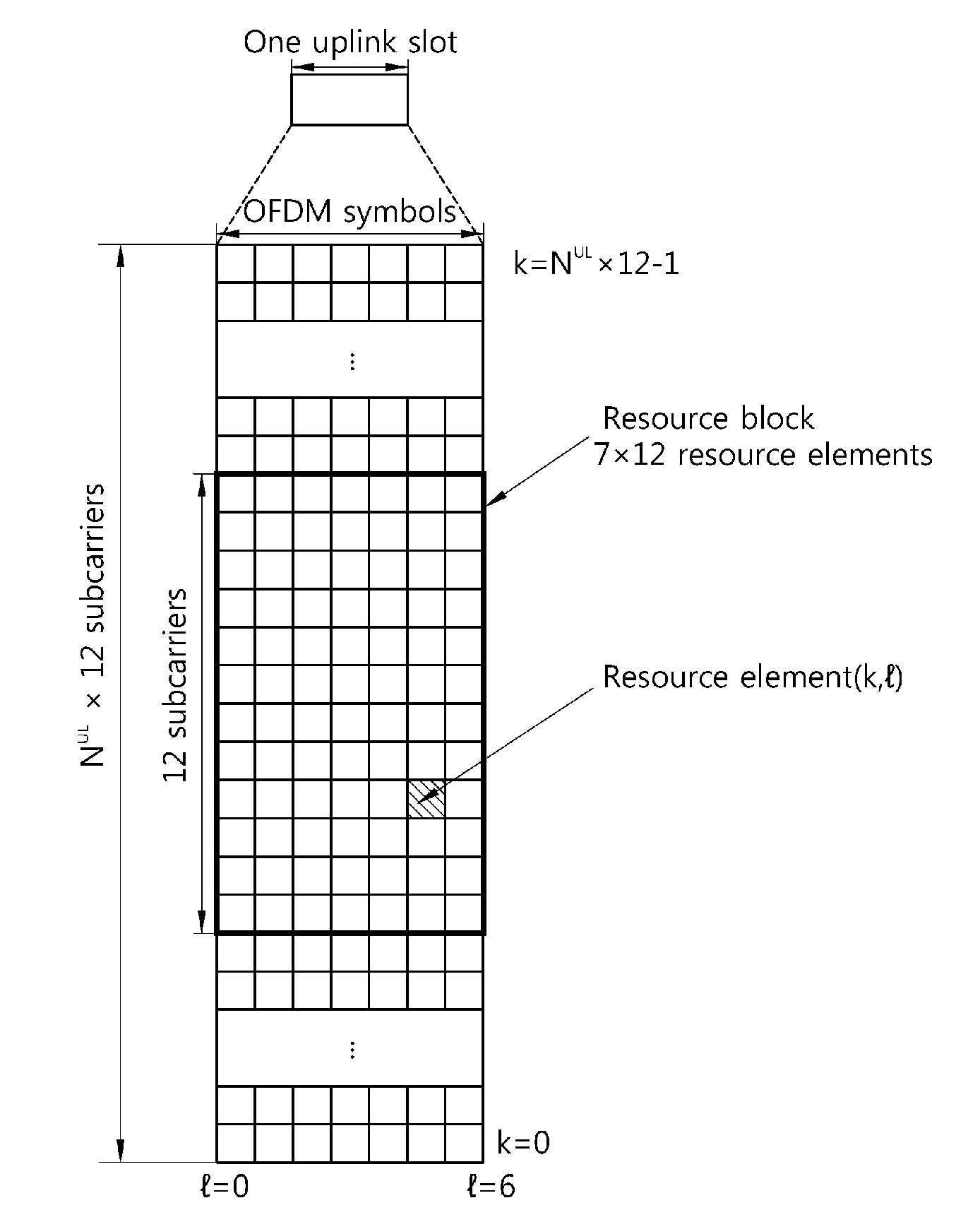
[0224]Here, each row may correspond to a subcarrier, and each column may correspond to an OFDM symbol. Each element of the matrix may be mapped to resource elements of RBs used for information transmission. Here, the matrix includes 12 rows and four columns, but it is merely illustrative and the number of rows and columns is not limited.
[0225]FIG. 19 shows an example of a single RB to which the rth spread sequence is mapped.
[0226]Referring to FIG. 19, the RB includes a slot (7 OFDM symbols) in the time domain and 12 subcarriers in the frequency domain. RS is carried on three of the seven symbols, and information is carried on the remaining 4 OFDM symbols (See FIG. 8).
[0227]The UE determines the rth OS index and the rth CS index by using the rth resource index. The UE generates the rth cyclically shifted sequence based on the rth CS index. The UE generates the rth modulated sequence based on the rth cyclically shifted sequence and the modulation symbol d(0) with respect to the information. The UE generates the rth spread sequence from the rth modulated sequence based on the rth OS index. Elements of the rth spread sequence may be represented by the following equation.
MathFigure 24
zr(n, k)=wr(k)·d(0)·r(n, Icsr)   [Math.24]
[0228]Here, n=0, . . . , 11, k=0, 1, 2, and 3, wr(k) is the kth element of the rth OS indicated by the rth resource index, Icsr is the rth CS index, and r(n,Icsr) is the rth cyclically shifted sequence.
[0229]The case of R=2 will be described for the sake of brevity. If R=2, the following three case can be considered in the third exemplary embodiment: (1) the case where the first and second CS indices are different and the first and second OS indices are the same, (2) the case where the first and second CS indices are different and the first and second OS indices are different, and (3) the case where the first and second CS indices are the same and the first and second OS indices are different. Each case will now be described.
[0230](1) If the First and Second CS Indices are Different and the First and Second OS Indices are the Same
[0231]For example, it is assumed that the first resource index indicates 0 as the first CS index and [1, 1, 1, 1] as the first OS. Also, it is assumed that the second resource index indicates 2 as the second CS index and [1, 1, 1, 1] as the second OS.
[0232]A first spread sequence z1(n,k) generated by using the first resource index transmitted through the first transmit antenna and a second spread sequence z2(n,k) generated by using the second resource index transmitted through the second transmit antenna may be represented by the following equation.
MathFigure 25 z 1 ( n , k ) = w 1 ( k ) · d ( 0 ) · r ( n ) · exp ( j 2 π · 0 · n 12 ) z 2 ( n , k ) = w 2 ( k ) · d ( 0 ) · r ( n ) · exp ( j2π · 2 · n 12 ) [ Math . 25 ]
[0233]Here, r(n) is a base sequence.
[0234]A reception signal y(n,k) may be represented by the following equation (0≦n≦11, 0≦k≦3, and n and k are integer).
MathFigure 26
y(n,k)=z1(n,k)h1+z2(n,k)h2+n(n,k)   [Math.26]
[0235]If a first estimated symbol obtained by despreading the first resource index from the reception signal is d′1(0) and a second estimated symbol obtained by despreading the second resource index from the reception signal is d′2(0), the first and second estimated symbols may be represented by the following equation.
MathFigure 27
d′1(0)=48d(0)h1+n′1
d′2(0)=48d(0)h2+n′2 [Math.27]
[0236]Here, if a cyclic shift is despread, a simple frequency coherent detector or an IFFT-based maximum likelihood (ML) detector may be used.
[0237]An estimated symbol d′(0) obtained by combining the first and second estimated symbols may be represented by the following equation.
MathFigure 28 d ′ ( 0 ) = d 1 ′ ( 0 ) h 1 * + d 2 ′ ( 0 ) h 2 * = ( 4 d ( 0 ) h 1 + n 1 ′ ) h 1 * + ( 4 d ( 0 ) h 2 + n 2 ′ ) h 2 * = 4 ( h 1 2 + h 2 2 ) d ( 0 ) + n ′ [ Math . 28 ]
[0238]In this manner, a diversity gain is obtained.
[0239](2) If the First and Second CS Indices are Different and the First and Second OS Indices are Different
[0240]For example, it is assumed that the first resource index indicates 0 as the first CS index and [1, 1, 1, 1] as the first OS. Also, it is assumed that the second resource index indicates 2 as the second CS index and [1, −1, 1, −1] as the second OS.
[0241]Also, in this case, the same diversity gain as that of the case (1) where the first and second CS indices are different and the first and second OS indices are the same is obtained.
[0242](3) If the First and Second CS Indices are the Same and the First and Second OS Indices are Different
[0243]For example, it is assumed that the first resource index indicates 0 as the first CS index and [1, 1, 1, 1] as the first OS. Also, it is assumed that the second resource index indicates 0 as the second CS index and [1, −1, 1, −1] as the second OS.
[0244]Also, in this case, the same diversity gain as that of the case (1) where the first and second CS indices are different and the first and second OS indices are the same is obtained.

PUM

no PUM

Description & Claims & Application Information

We can also present the details of the Description, Claims and Application information to help users get a comprehensive understanding of the technical details of the patent, such as background art, summary of invention, brief description of drawings, description of embodiments, and other original content. On the other hand, users can also determine the specific scope of protection of the technology through the list of claims; as well as understand the changes in the life cycle of the technology with the presentation of the patent timeline. Login to view more.

Similar technology patents

Superposition coding

InactiveUS20100046644A1Reduce complexityImprove performanceMultiple modulation transmitter/receiver arrangementsSecret communicationSuperposition codingEngineering
Owner:MOTOROLA MOBILITY LLC

Vertical adaptive antenna array for a discrete multitone spread spectrum communications system

InactiveUS20050002440A1Improve performanceImprove signal-to-interference levelPolarisation/directional diversityMultiplex code allocationSpatially adaptiveSelf adaptive
Owner:AT&T MOBILITY II LLC

Classification and recommendation of technical efficacy words

Why Eureka
Try Eureka