
Heating ventilation air condition system

Inactive Publication Date: 2011-07-14
ENOCEAN
View PDF13 Cites 35 Cited by
  • Summary
  • Abstract
  • Description
  • Claims
  • Application Information

AI Technical Summary

Benefits of technology

[0015]It can have a wireless communication system to communicate with one or more sensors and other control units or a centralized controller so that no wires are required for data communication. As a result, the air vent and the actuator can be easily installed in new ducts or installed as a replacement of the existing vent cartridge.
[0016]Further, the invention provides a method for operating the above system. The method allows a reduction of energy consumption by placing at least the actuator in sleep mode. The efficiency of the system can be improved by redistributing air from one zone to another tone.

Problems solved by technology

This often results in uncomfortable temperatures in one or another area of the home.
However, this results in only minor improvement in comfort:Air vents are often located behind furniture or ceiling-mounted.
This cannot be accomplished by conventional HVAC systems.If a large portion of the home is unoccupied, energy is wasted conditioning these rooms.
However, they still do not enable individual room control.
Many VAVs rely upon manual adjustment, e.g. twisting a knob to open or close the vent. however, these vents are usually located on ceilings and are not easily reached.
The cost and time required for installing such automated VAVs can be high.

Method used


Image

  • Heating ventilation air condition system
  • Heating ventilation air condition system
  • Heating ventilation air condition system

Examples


Embodiment Construction

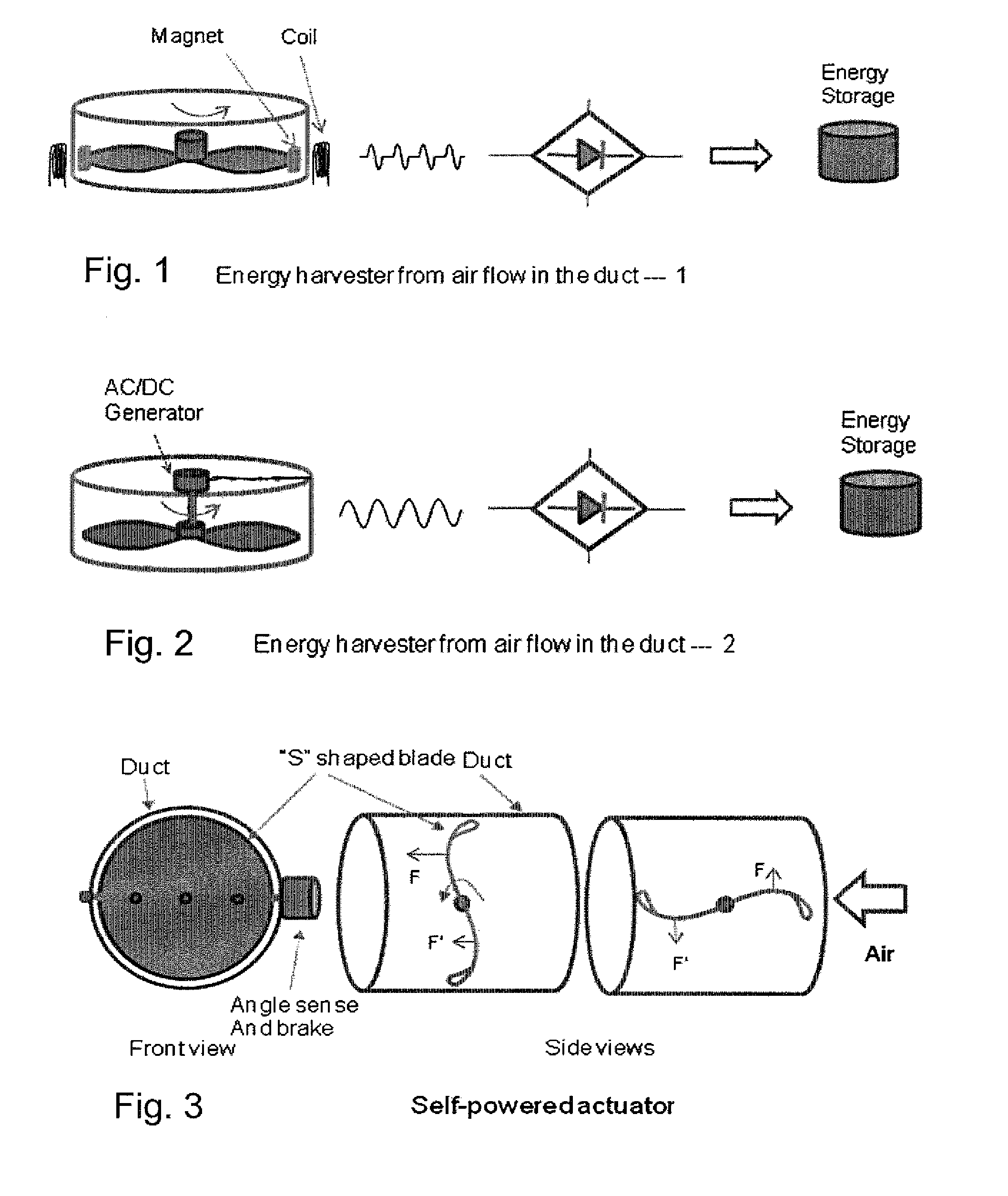
[0026]The following are embodiments energy harvesters which harvest energy from the ambience. Several different kinds of harvesters can be used together.

[0027]FIG. 1 shows an energy harvester comprising rotating blades that turn when air flows over the blades. Magnets mounted on the blades rotate past coils mounted on the perimeter. When the magnets pass the coil the magnetic flux in the coil changes and generates an electrical current in the coil.

[0028]FIG. 2 shows an energy harvester comprising an AC or DC generator directly coupled with the shaft of a rotating propeller. An AC generator is preferred because it has no commutator and brushes and is thus more robust and less noisy. In both figure the voltage is rectified and used to charge an energy storage device such as a capacitor or a rechargeable battery.

[0029]In another configuration, the propeller shaft winds a spring to store mechanical potential energy. The spring is used as the energy source to open and close the air vent....


PUM


Abstract

A heating ventilating air condition system, comprising an adjustable air vent, configured to control the rate of air flow rate through the vent, an actuator, configured to control the adjustable air vent, and an ambient energy harvester, configured to supply energy to the actuator, wherein the energy required for operating the actuator is provided by the ambiance.

Description

CROSS-REFERENCE TO RELATED APPLICATION[0001]This application claims priority to U.S. Provisional Application Ser. No. 61 / 132,351, filed Jun. 18, 2008, and which is incorporated herein by reference in its entirety.FIELD OF THE INVENTION [0002]The invention relates to a heating ventilating air condition (HVAC) system.BACKGROUND OF THE INVENTION [0003]A typical residential home has only one thermostat, usually located in the main living area, which controls the temperature for the whole home. For various reasons, such as the orientation to the sun, upstairs vs. basement, cooking in the kitchen, different insulation, amount of windows, etc., the temperature throughout the home may vary significantly (10° F.) from the temperature at the thermostat. This often results in uncomfortable temperatures in one or another area of the home. An occupant can change the air flow to a particular room by manually adjusting the vents. However, this results in only minor improvement in comfort:[0004]Air...

Claims


Application Information

Patent Timeline
IPC IPC(8): G05D23/19F24F5/00
CPCF24F5/0042F24F5/0046Y02B30/78F24F11/0017F24F11/0001F24F11/30F24F2110/50Y02B30/70F24F11/46F24F11/74
Inventor SCHMIDT, FRANKEGGERT, HOLGER ALFONSBREHLER, MARKUSYOU, EUGENEO'CALLAGHAN, JIM
Owner ENOCEAN
Learn More