Dispensing capsule

a technology of capsules and capsules, applied in the field of capsules, can solve the problems of time-consuming and often messy process, product stability, strength and effectiveness not retained, etc., and achieve the effects of convenient identification, faster rate and higher reliability

Active Publication Date: 2011-07-21
GENESEE REGIONAL BANK
View PDF60 Cites 103 Cited by
  • Summary
  • Abstract
  • Description
  • Claims
  • Application Information

AI Technical Summary

Benefits of technology

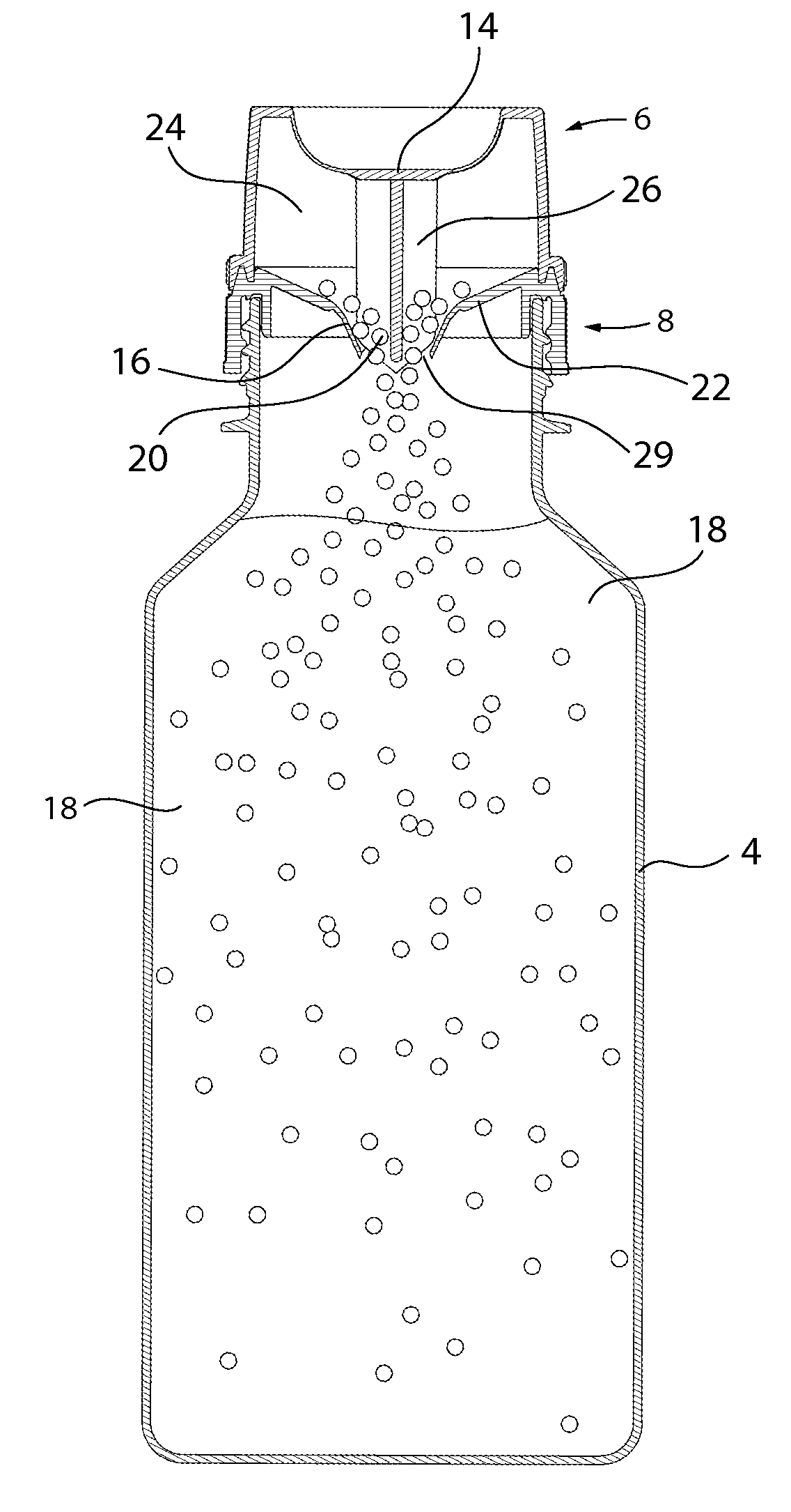
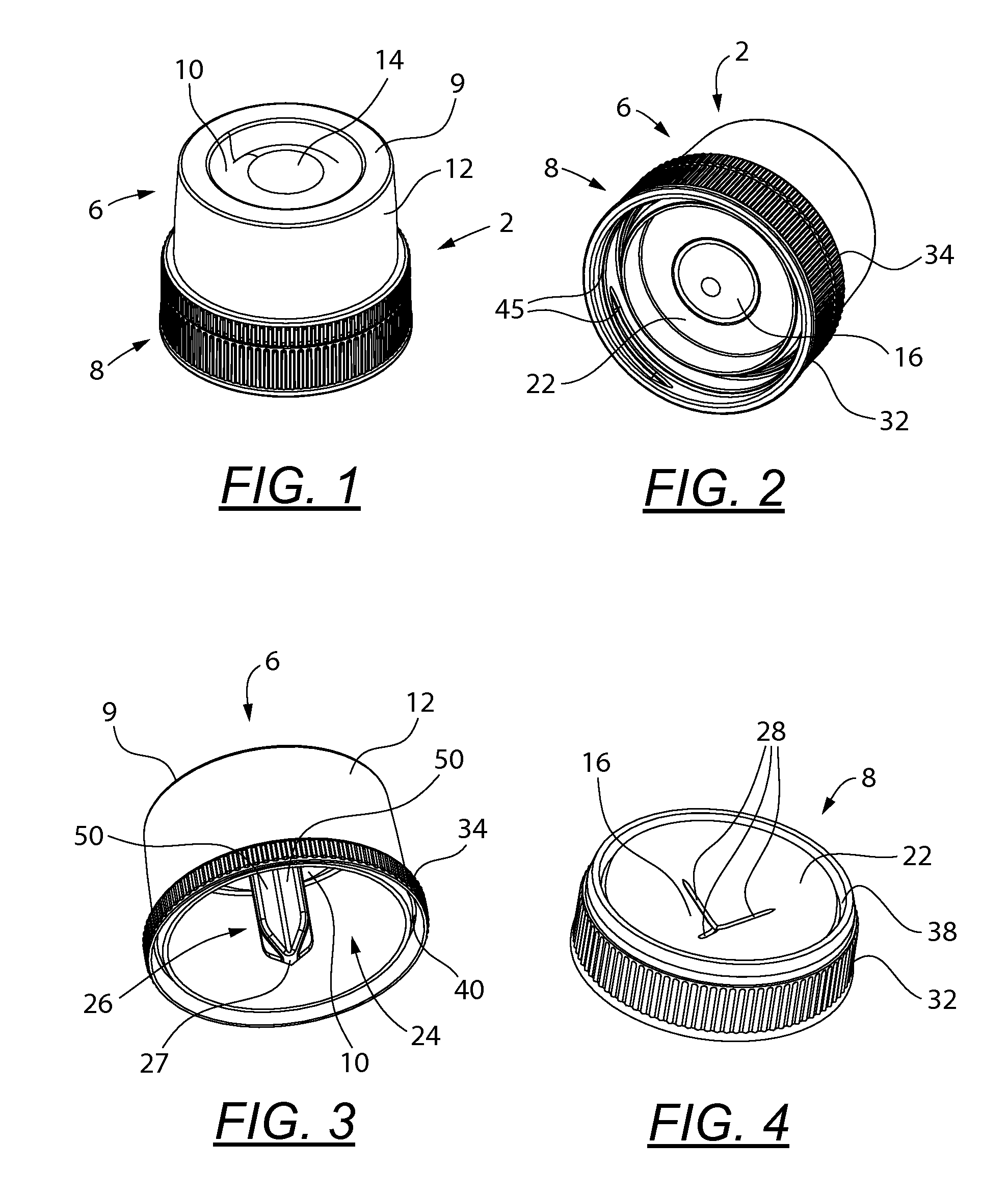
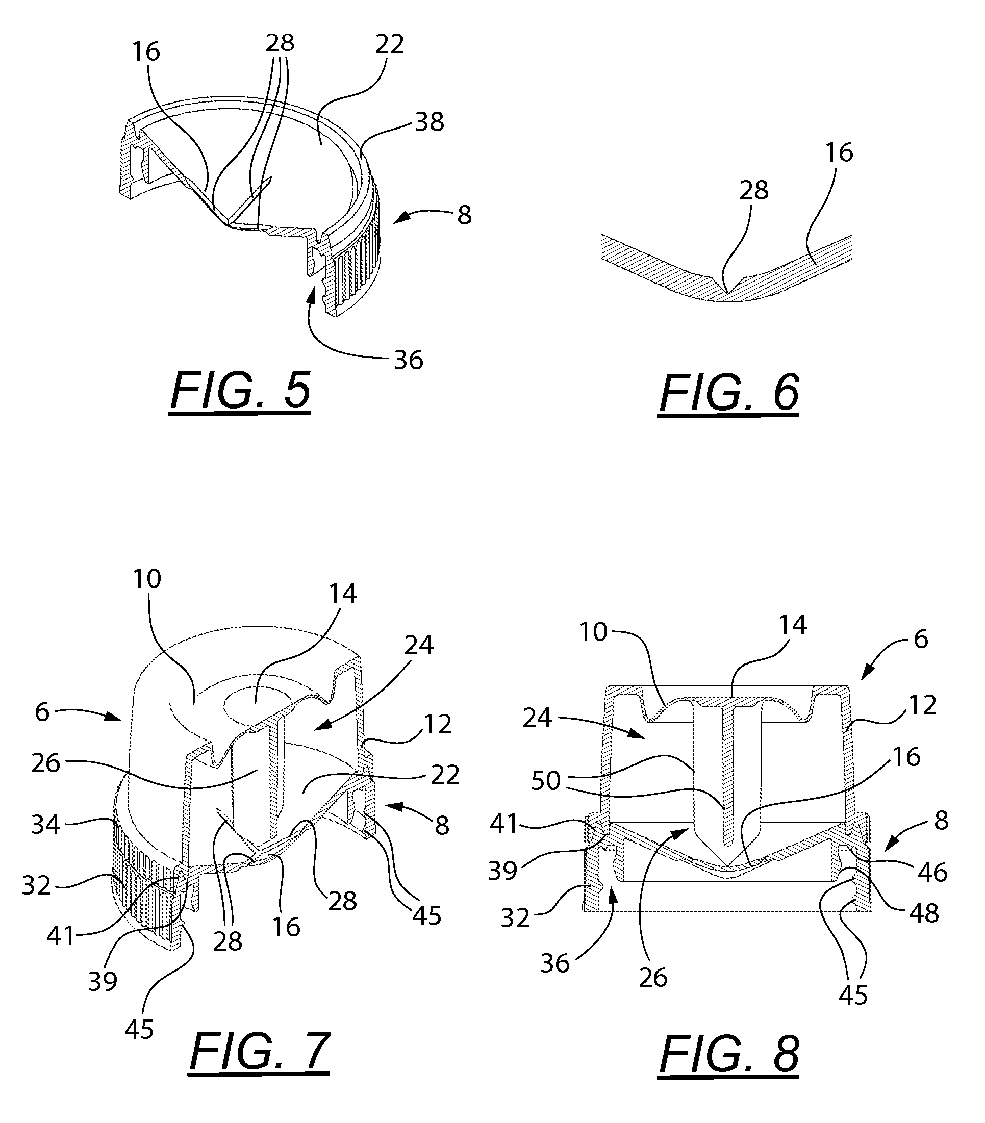
[0034]Partially detached breakaway flaps obstruct the dispersion path of the dispensing capsule's contents. The present device provides a dispersion capsule with a stake that is injection molded with and thus integrally part of the diaphragm button such that it does not fall into the fluid cavity after an aperture allowing fluid communication between the capsule's contents and the fluid cavity has been opened. This provides the additional advantage that loose non-consumable material from the opening operation is not introduced into the consumable solution. Obstruction is further minimized by the present device by providing a conically shaped base plate such that the inclined surface urges full dispersion of the contents into the fluid cavity of a receiving container.
[0035]Prior art dispensing caps fully or partially conceal the contents from the user or potential consumer, especially with a double side wall structure. In the present invention, the single wall cup functions to prominently display its contents above the attached bottle. By eliminating a dual side wall structure, the contents are more visible to a user for easy identification.
[0015]The cup preferably comprises a diaphragm functioning as a top wall in communication with a cylindrical-shaped sidewall. A base plate is located on the base correspondingly in communication with the cylindrical-shaped sidewall when the cup-base unit is assembled or jointed together. The base plate is conical shaped to promote the flow of the cap contents through the aperture and into the attached bottle. The base plate is concentrically but opposingly disposed from a button. The tear lines are concentrically disposed on the base plate. The button and stake are coaxially aligned and operably connected to one another. In use, the stake extends through an aperture made in the base plate.
[0037]The base plate is formed of a thin polymer plate and is thicker and more durable than a typical thin film membrane. Its mechanism of rupture relies on the stake mechanism rather than the fragility of the plate. This durable base plate and flexible diaphragm allow the dispensing capsule to withstand high gauge pressure differential between the fluid cavity and the capsule cavity of over 14 psi (9.653 e+004 newtons / square meter) and to withstand the rigors of transportation, handling and storage that often cause aperture trauma.
[0038]The dispensing capsule is formed by two easily jointed components, a cup and a base, that can be spin welded, providing several advantages over ultrasonic welding: lower power consumption, higher strength hermetic weld, more reliable welding of polypropylene and polyethylene. This ease of jointing the cup and base components during the pre-filling process simplifies the manufacturing process.
[0039]While prior art dispensing caps use a flat membrane that is ruptured by a stake, such a ruptured membrane is not conducive to material flow down and out of the dispenser, causing mixing problems and problems with residual material in the dispenser when the dispenser, affixed to a drinking bottle, is removed for drinking (material dripping from cap). The dispensing capsule provides an inclined base plate and aperture to funnel material (powder, water mixture) out of the capsule. Furthermore, an inclined (cone shaped) surface is provided at the stake's base such that capsule material contacting the interior surface of the diaphragm button is pushed sideways, away from the stake to facilitate movement of the stake towards the plate.

Problems solved by technology

Some of these products do not retain their stability, strength and effectiveness for long after they have been mixed in solution or suspension, yet the product can be stored for extended periods of time if one ingredient is maintained separate from the other.
Manufacturers are presented with a number of challenges in merchandising of products of this genre.
Consumers are also presented a number of challenges in using these products.
However, the inconveniences associated with the use of such large containers of powders or mixes is well known.
Consumers must undertake the time-consuming and often messy process of properly combining and mixing the powder with a container of liquid, measuring and depositing the appropriate amount of liquid or powder within the container and, thereafter, shake, stir or otherwise fully mix the combined contents.
In doing so, powder and / or powder-liquid mix often spills, resulting in mess and partial loss of product.
There are several drawbacks and limitations with the prior art containers of this type and design.
These multiple component designs are more expensive to manufacture and offer a less reliable seal that is subject to mechanical failure under pressure or temperature changes that accompany transportation and long term storage of the end product.
Thus, the seal is not a hermetic one and the contents are subject to spoilage or contamination prior to use (consumption).
This dispensing cap overcomes many of the prior art problems, however, the mechanism is not ideal for all applications.
If the weld was defective, this small plunger could detach and end up in the drink, causing a choking hazard.
However, this device does not store and release material.
However, this frangible membrane has drawbacks.
The frangible membrane is inherently more delicate and may not hold up to environmental conditions typically encountered by drink bottles.
Moreover, these designs do not promote material flow from the cap into the liquid in an attached bottle.

Method used


Image

  • Dispensing capsule
  • Dispensing capsule
  • Dispensing capsule

Examples


Embodiment Construction

[0174]The use of conventional liquid containers such as plastic bottles for carrying water, juices, and other desirable liquids for human consumption is quite well known. The present device is generally directed, although not so limited, to a dispensing capsule that may be used with such bottles or containers to separately store an ingredient to be mixed with a liquid at the time of consumption to form a consumable solution or suspension. The dispensing capsule may also be used with other types of receiving containers where separate storage of one ingredient for mixing with a liquid at the time of use is desirable. In describing the preferred and alternate embodiments of the present device, as illustrated in the Figures, specific terminology is employed for the sake of clarity. The invention, however, is not intended to be limited to the specific terminology so selected, and it is to be understood that each specific element includes all technical equivalents that operate in a simila...


PUM


Abstract

A dispensing capsule has a diaphragm button, stake and frangible membrane for a system for selectively dispersing the contents of a cup into an attached bottle. A frangible membraned cup has a diaphragm button operably attached to a stake with the stake's sharp point at one end and the diaphragm button on the opposing end. A cavity is disposed in the cup for consumable product defined by side walls and a base plate. Preloaded ingredients contained within the hermetically sealed cup are discharged from the dispensing capsule into a bottle by simply depressing a button disposed on the diaphragm of the cup, thereby actuating the stake to thrust forward and apply concentrated pressure abaxially to the frangible membrane. This concentrated pressure pierces substantially the center of the frangible membrane, causing it to rupture and progressively opening it. The diaphragm button locks in this downward position, holding the stake into the opened frangible membrane to maintain the opening, permitting the contents to flow through the frangible membrane and exit the cavity of the cup.

Description

PRIORITY AND RELATED APPLICATIONS[0001]This application claims the benefit of priority from provisional application U.S. Ser. No. 61 / 296,283 filed Jan. 19, 2010 entitled “Bottle Top Dispensing Capsule”. The disclosure of said application is incorporated by reference herein in its entirety.FIELD OF THE INVENTION[0002]The present device relates generally to dispensing capsules, and more specifically, to a dispensing capsule for removable engagement with a liquid-containing bottle and enabling dry or liquid ingredients contained within the dispensing capsule to be conveniently deposited into a bottle and mixed with the liquid contents thereof.BACKGROUND OF THE INVENTION[0003]Many products are sold as liquid concentrates, crystals and powders to be mixed with a liquid prior to consumption or use. Such products include foods, drugs, cosmetics, adhesives, polishes, cleansers, dyes, infant formula, drink mixes, meal replacements, protein powders, energy mixes, supplements, nutritional prod...

Claims


Application Information

Patent Timeline
Patent Type & Authority Applications(United States)
IPC IPC(8): B65D51/28
CPCB65D21/0213B65D2251/023B65D51/2835
Inventor COON, DARREN
Owner GENESEE REGIONAL BANK
Why Eureka
Try Eureka