Identification card apparatus

a technology of identification card and card body, which is applied in the direction of electrical devices, instruments, computing, etc., can solve the problems of short transmission range between the antenna and the reader, increasing inconvenience of use, and restricted overall dimensions and weight of the active rfid tag, so as to improve the connection relationship, extend the transmission range, and optimize the configuration of internal components

Inactive Publication Date: 2011-07-21
WADEGARCIA & ASSOCS +2
View PDF7 Cites 2 Cited by
  • Summary
  • Abstract
  • Description
  • Claims
  • Application Information

AI Technical Summary

Benefits of technology

[0008]As per the aforementioned issues, a primary objective of the present invention is to provide an identification card apparatus which optimizes the configuration of internal components and improves their connection relationship as per the structural design perspecti...

Problems solved by technology

Yet, due to the restrictions of the present wireless communication technology implemented between the antenna and the external devices (reader), the transmission range between the antenna and the reader is short.
Users need to put the passive RFID tag extremely close to the reader for detecting, thereby increasing inconvenience of use.
However, the overall dimensions and weight of the active RFID tag are restricted by...

Method used


Image

  • Identification card apparatus
  • Identification card apparatus
  • Identification card apparatus

Examples


first embodiment

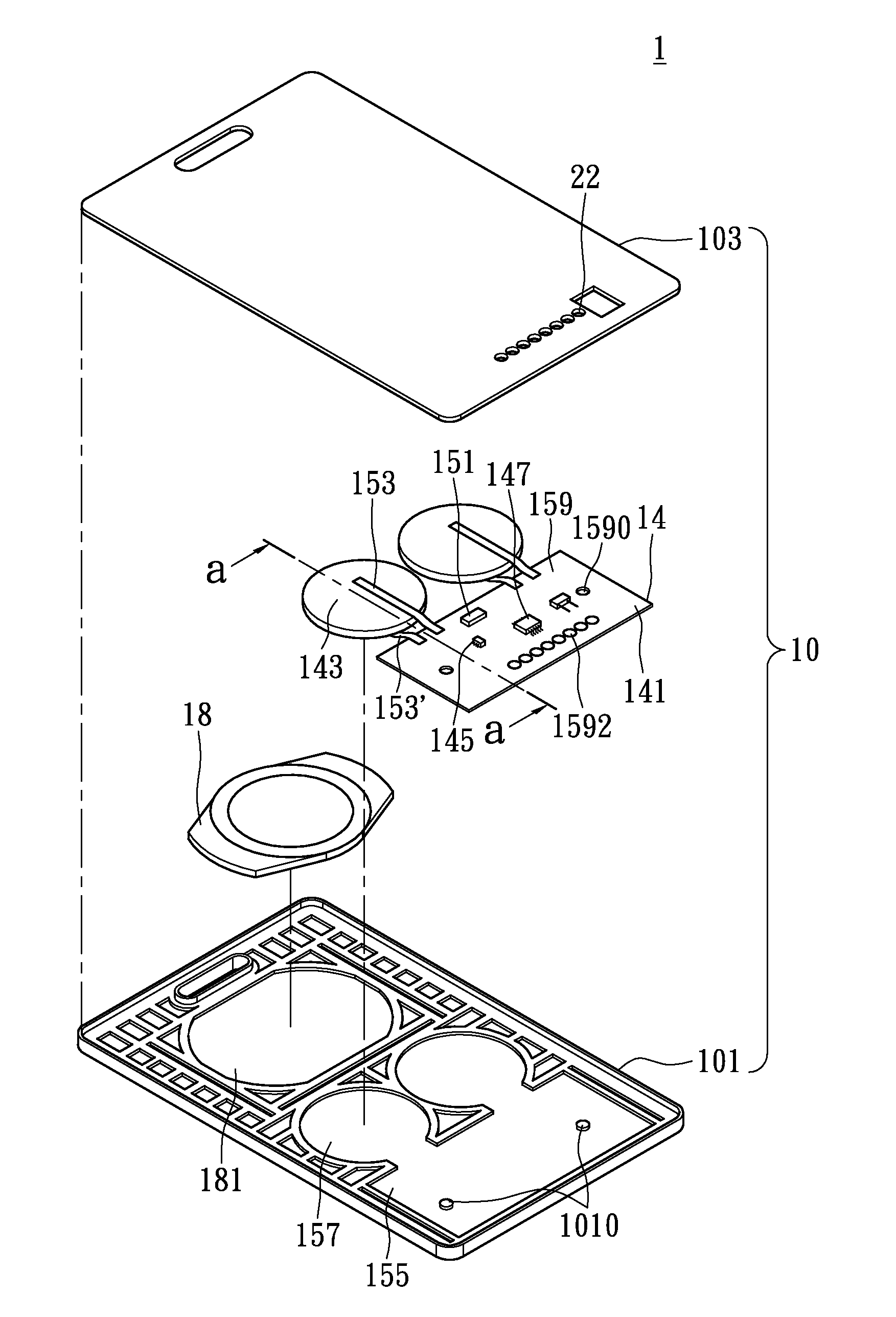
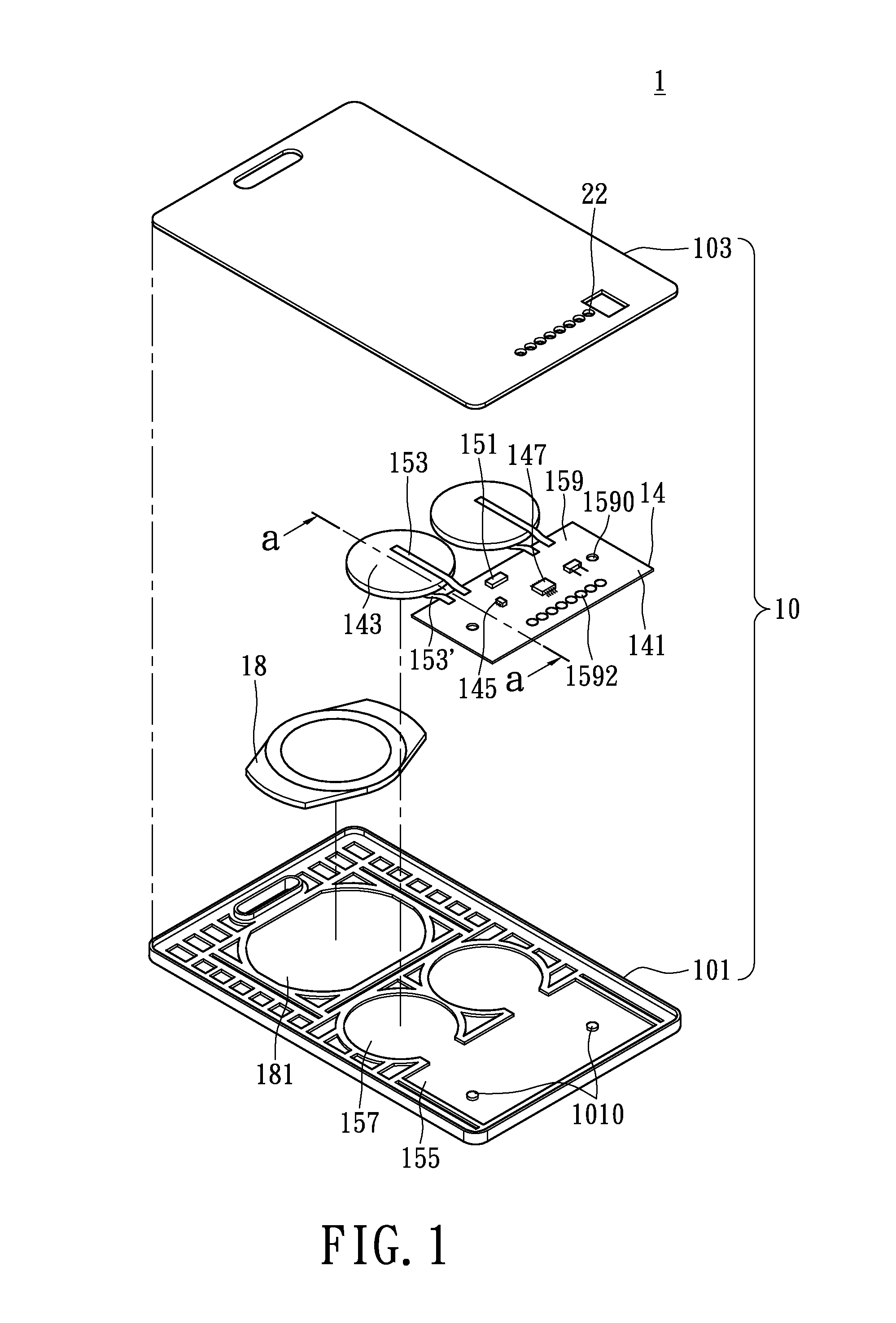
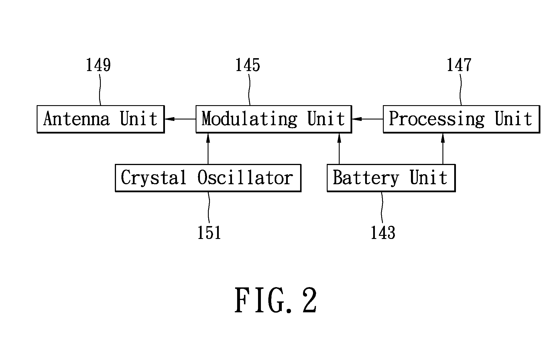
[0023]Next please refer to FIG. 2 in conjunction with FIG. 1, in which a block diagram of the first embodiment in accordance with the identification card apparatus according to the present invention is demonstrated. The circuit design of the integrated circuit board 141 includes a plurality of electrical elements for storing, processing, and transmitting identification signals automatically. The processing unit 147 of the integrated circuit board 141 disposed on the printed circuit board 159, and electrically connected with the battery unit 143 for power supply, transmits a radio frequency signal automatically within a predetermined period to the modulating unit 145. The modulating unit 145 disposed on the printed circuit board 159, and electrically connected with the battery unit 143, the processing unit 147, and the crystal oscillator 151. The frequency, the phase, or the amplitude associated with the audio frequency signal outputted from the processing unit 147 is modulated by th...

second embodiment

[0029]Next please refer to FIG. 4, in which an exploded diagram of the identification card apparatus in accordance with certain aspects of the present technique is demonstrated. The connection relationship of an identification card apparatus 1a is identical to that of FIG. 1 except of that the structure design of the second housing member 103a is altered by adding an opening 1030. The position of the opening 1030 of the second housing member 103a is designed with respect to the location of the third accommodating space 181 in the first housing member 101. Per user's specific needs, the passive radio frequency identification module 18 can be disposed inside the third accommodating space 181 thru the opening 1030 designed on the second housing member 103a.

[0030]As shown in FIG. 5, the identification card apparatus 1a can not only be used as a general identification card, but also used as an accessing card to certain specific areas which have higher security. For example, while facult...

third embodiment

[0031]Next please refer to FIG. 6 in conjunction with FIG. 1, in which an exploded diagram of the identification card apparatus in accordance with certain aspects of the present technique is demonstrated. The connection relationship of the identification card apparatus 1 is identical to that of FIG. 1 except of adding an overlay 16. A side of the overlay 16 has a back adhesive for attaching on the second housing member 103, and the other side of the overlay is printed with a text 161, an image 163, or a barcode 165, etc. Thus, the identification card apparatus 1 can not only apply both the active radio frequency identification module and the passive radio frequency identification module, but also incorporate with the barcode 165 to extend the application field. For example, the card according to the embodiment can be used as a library card, or the like. It is worth mentioning that as the overlay 16 attached on the second housing member 103, the plurality of through holes 22 can also...


PUM


Abstract

An identification card apparatus is provided. The identification card apparatus includes a main body formed by a first housing member and a second housing member and an active radio frequency identification module which includes a battery unit having at least one coin cell, an integrated circuit board and a plurality of conductive connecting pieces. One end of the conductive connecting piece connects to a side of the coin cell, and the other end of the conductive connecting piece connects to a surface of the integrated circuit board, thereby forming a bending portion for the conductive connecting piece. Consequently, by improving the structural design of internal elements and their connection relationship, the identification card apparatus can extend the transmission range, reduce the overall dimension in thickness and weight, enhance the connection relationship of the internal elements, and increase vibration resistance, thereby improving convenience of use.

Description

BACKGROUND OF THE INVENTION[0001]1. Field of the Invention[0002]The present invention relates to an identification card apparatus, in particular, to a slim and anti-vibration active type identification card apparatus.[0003]2. Description of Related Art[0004]As the radio frequency identification (RFID) chip technology advances and the manufacturing cost decreases, the radio frequency identification technology is applied widely. Generally speaking, a radio frequency identification system contains a reader and a RFID tag basically, wherein the RFID tag is composed of a radio frequency identification integrated circuit and an antenna. The RFID tags can also be classified into two types, one is an active type, which contains a power source and can transmit signals; and the other one is a passive type, which has no power source and requires an external power source.[0005]A passive RFID tags can receive a scanning signal emitted from the RFID reader. The electrical energy contained in the ...

Claims


Application Information

Patent Timeline
IPC IPC(8): H04Q5/22
CPCG06K19/0723G06K19/0702
Inventor CHEN, HUNG-YUANHWANG, HSIUNG-ILU, KUO-PENG
Owner WADEGARCIA & ASSOCS
Why Eureka
Try Eureka