Coated articles with heat treatable coating for concentrated solar power applications, and/or methods of making the same

a technology of concentrated solar power and coatings, which is applied in the direction of superimposed coating process, lighting and heating apparatus, instruments, etc., can solve the problems of reducing the thermal efficiency of fresnel power plants, etc., to achieve the effect of increasing the solar reflectance, increasing the operating temperature of the panel, and increasing the steam outpu

Inactive Publication Date: 2011-07-21
GUARDIAN GLASS LLC
View PDF3 Cites 34 Cited by
  • Summary
  • Abstract
  • Description
  • Claims
  • Application Information

AI Technical Summary

Benefits of technology

[0005]In a CSP plant, a secondary reflector panel typically helps heat an absorber tube that is filled with water or other heating fluid. The water is converted into steam with a temperature of about 270 degrees C. and a pressure of 55 bar. The steam is used to drive a turbine-generator unit, thereby producing electrical power. The overall efficiency of the Fresnel reflector solar power generating system thus is tied to the temperature and pressure of the produced steam. Increasing the solar reflectance generated by the secondary mirror panel and increasing the operating temperature of the panel increases the energy input to the steam. This directly increases the power and thermal efficiency of the Fresnel power plant. This efficiency limitation is a driver for the competitiveness of this technology versus other solar thermal technologies such as parabolic trough and central receivers.

Problems solved by technology

Conventional SRPs, when installed as part of the secondary reflector assembly, often experience problems (e.g., do not function or are otherwise limited) when a maximum operating temperature of about 270 degrees C. is met or exceeded.
These changes degrade the solar reflective performance of the aluminum surface and prevent the generated temperatures from exceeding about 270 degrees C. in the SRP assembly unit.
This efficiency limitation is a driver for the competitiveness of this technology versus other solar thermal technologies such as parabolic trough and central receivers.

Method used


Image

  • Coated articles with heat treatable coating for concentrated solar power applications, and/or methods of making the same
  • Coated articles with heat treatable coating for concentrated solar power applications, and/or methods of making the same
  • Coated articles with heat treatable coating for concentrated solar power applications, and/or methods of making the same

Examples


Embodiment Construction

[0019]The following description is provided in relation to several example embodiments which may share common characteristics, features, etc. It is to be understood that one or more features of any one embodiment may be combinable with one or more features of other embodiments. In addition, single features or a combination of features may constitute an additional embodiment(s).

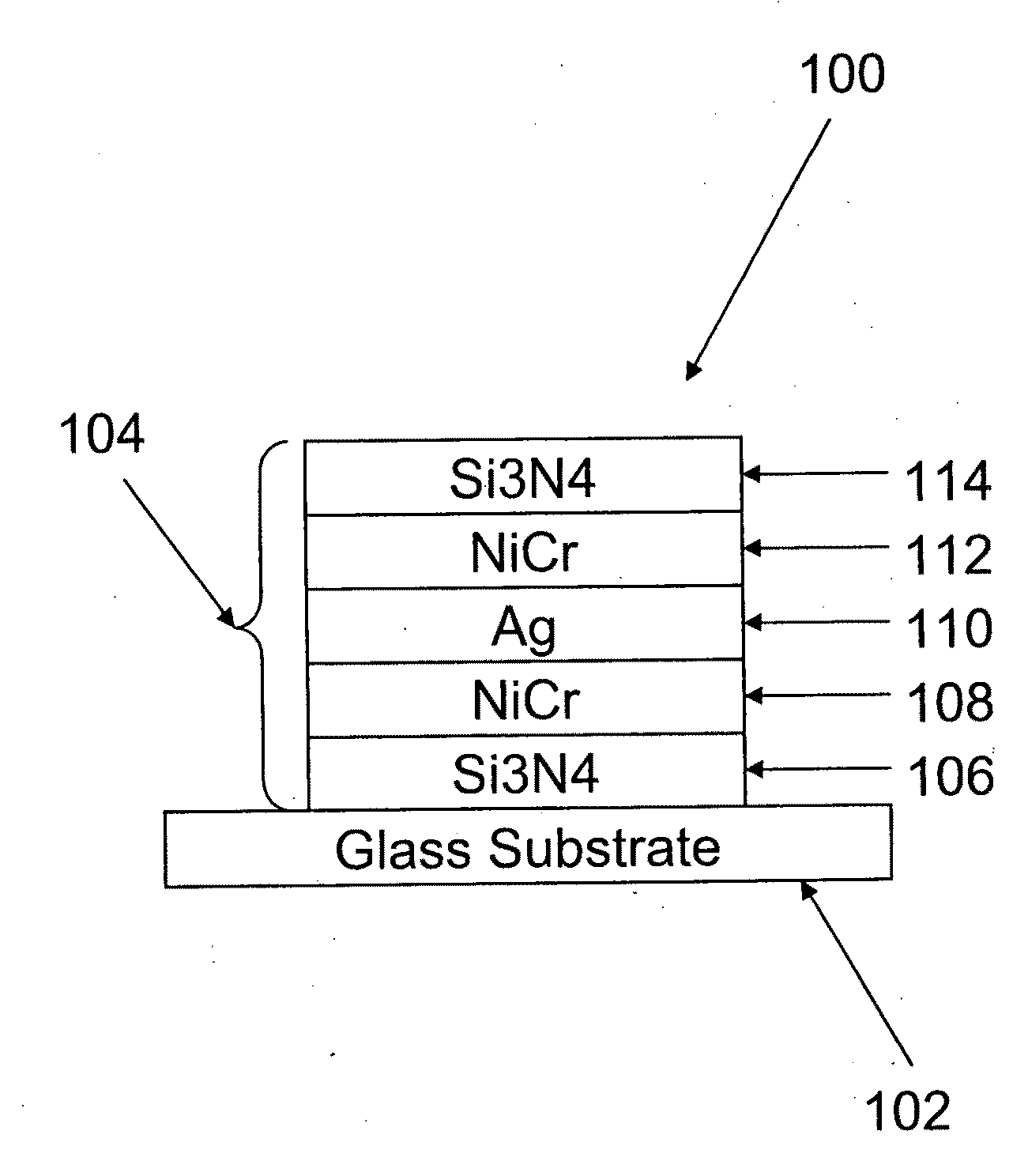
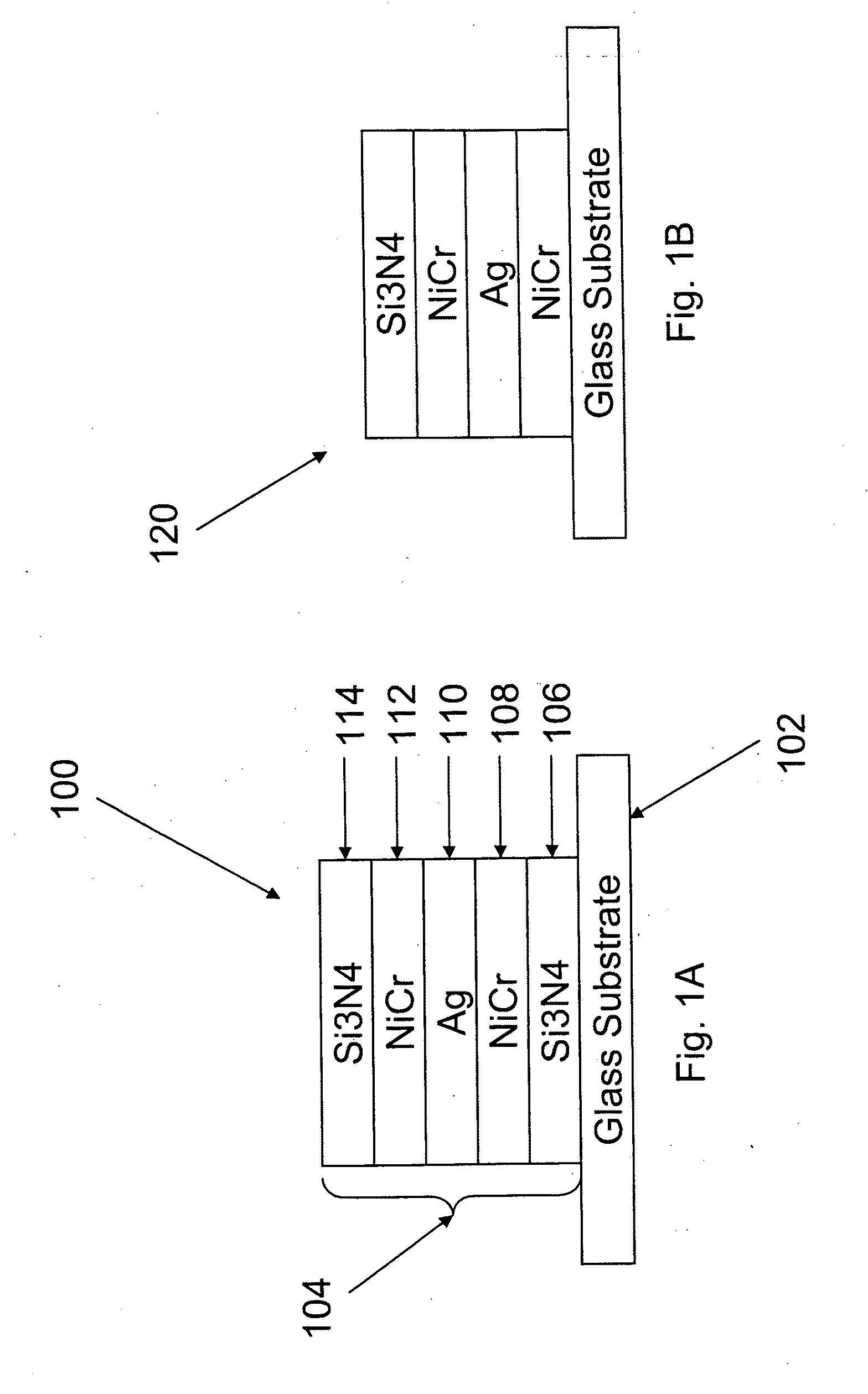
[0020]Certain exemplary embodiments relate to an improved (e.g., high performance) secondary reflector panel (SRP) that may be used in concentrating solar power applications (CSP applications), such as, for example, Fresnel CSP designs. The coated product includes a high performance secondary reflector (e.g., mirror) that may be bent after coating to the desired reflector shape. Alternatively, or in addition, the product may be optionally fritted, painted, or laminated to protect the mirrored surface. The secondary mirror may include a sputtered silver-inclusive or silver-based coating onto a glass substrate. ...


PUM

PropertyMeasurementUnit
thickaaaaaaaaaa
solar reflectanceaaaaaaaaaa
pressureaaaaaaaaaa

Abstract

Certain example embodiments relate to heat treatable coated articles, e.g., suitable for concentrating solar power (CSP) and/or other applications. For instance, the heat treatable coated article may be a secondary reflector panel, primary reflector, etc., where a reflective coating is disposed on a glass substrate. A portion of the reflective coating may be removed and a frit material is disposed over the reflective coating. An elevated temperature may be applied to the glass substrate, the coating, and the frit material where the frit is cured. The coated article may be left flat, or optionally cold- or hot-bent into a desired shape suitable for a desired application.

Description

[0001]This application claims the benefit of U.S. Application Ser. No. 61 / 282,307, filed on Jan. 19, 2010, the entire contents of which are hereby incorporated herein by reference. The application also is related to U.S. application Ser. No. 12 / 929,087, the entire contents of which are hereby incorporated herein by reference.FIELD OF THE INVENTION[0002]Certain example embodiments of this invention relate to coated articles with heat treatable coatings for concentrated solar power (CSP) applications, and / or methods of making the same. More particularly, certain example embodiments of this invention relate to making a reflector panel with a reflective coating and a frit material backing by curing the frit material, bending the substrate, and heat treating the substrate with the coating thereon during a common heating process. In other words, in certain example embodiments, the substrate is bent and the frit material is cured, while the substrate with the coating and frit material ther...

Claims


Application Information

Patent Timeline
Patent Type & Authority Applications(United States)
IPC IPC(8): G02B5/08C03C17/34B05D5/06F24S23/70F24S23/79
CPCF24J2/1057F24J2/18G02B5/0858Y02E10/40C03B23/025C23C28/30C03C17/3618C03C17/3644C03C17/3663C03C17/3639C03C17/361C03C8/02C03C17/3626C03C17/3652C03C17/366F24S23/82F24S23/79
Inventor LU, YIWEIMAIKOWSKI, DAVID P.LINGLE, PHILIP J.PRONE, DANIEL F.
Owner GUARDIAN GLASS LLC
Why Eureka
Try Eureka