Workpiece breakage prevention method and apparatus

a technology for workpieces and heat treatment equipment, applied in heat treatment equipment, testing/measurement of semiconductor/solid-state devices, manufacturing tools, etc., can solve problems such as introducing a source of measurement error, affecting the accuracy of workpiece heat treatment, and reducing the deformation of the wafer

Active Publication Date: 2011-07-21
MATTSON TECHNOLOGY +1
View PDF33 Cites 16 Cited by
  • Summary
  • Abstract
  • Description
  • Claims
  • Application Information

AI Technical Summary

Benefits of technology

[0038]The means for modifying may include means for counteracting thermal runaway in the wafer. The means for modifying may include means for increasing a spacing between the wafer and a support plate therebeneath.
[0039]The means for modifying may include means for reducing a deformation of the wafer relative to its initial shape. The means for modifying may include means for supplying additional heat to a surface of the wafer. The means for modifying may include means for aborting the thermal processing of the wafer.

Problems solved by technology

This may also tend to produce thermal deformation of the wafer.
For example, the present inventors have observed that measurements of electromagnetic radiation emitted or reflected by a surface of the wafer may be susceptible to measurement errors caused by the deformation of the wafer.
For example, if reflectivity of a surface of the wafer is being measured, the intensity of illuminating radiation reflected by the wafer and received at a detector will change as the wafer thermally deforms from a planar shape to a dome shape, due to the magnification or spherical lensing effect associated with the thermally deformed dome shape of the wafer, thereby introducing a source of measurement error.
If such a reflectivity measurement is being used to produce an emissivity-compensated temperature measurement, such a temperature measurement will also suffer from such measurement errors.

Method used


Image

  • Workpiece breakage prevention method and apparatus
  • Workpiece breakage prevention method and apparatus
  • Workpiece breakage prevention method and apparatus

Examples


Embodiment Construction

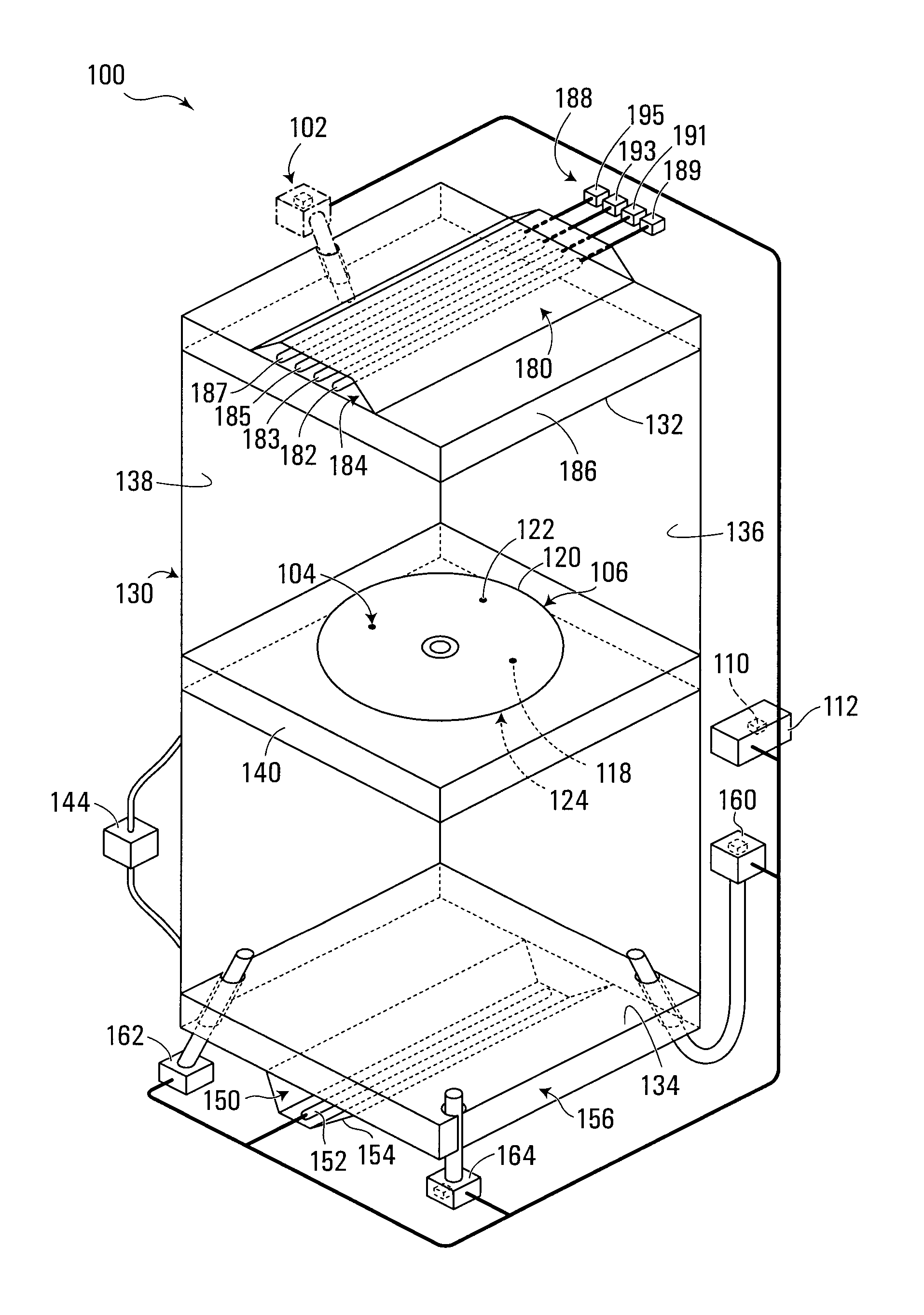
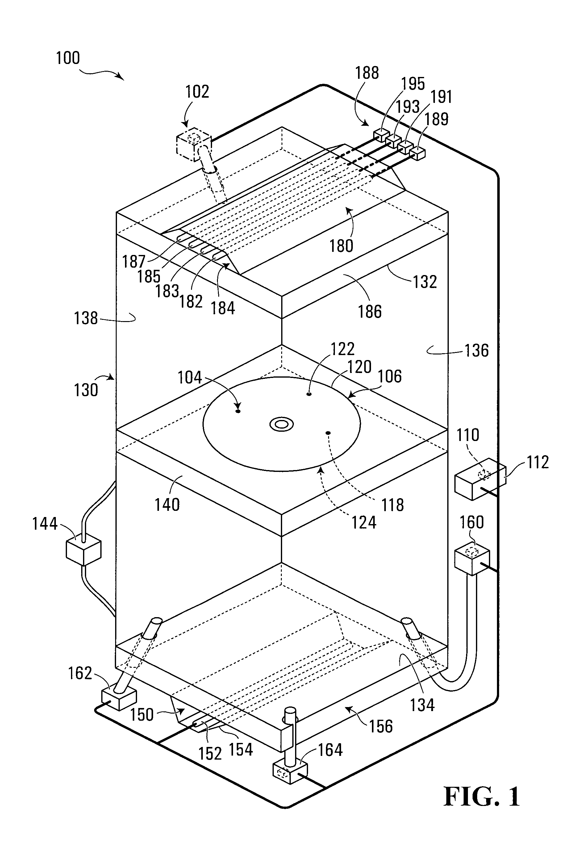
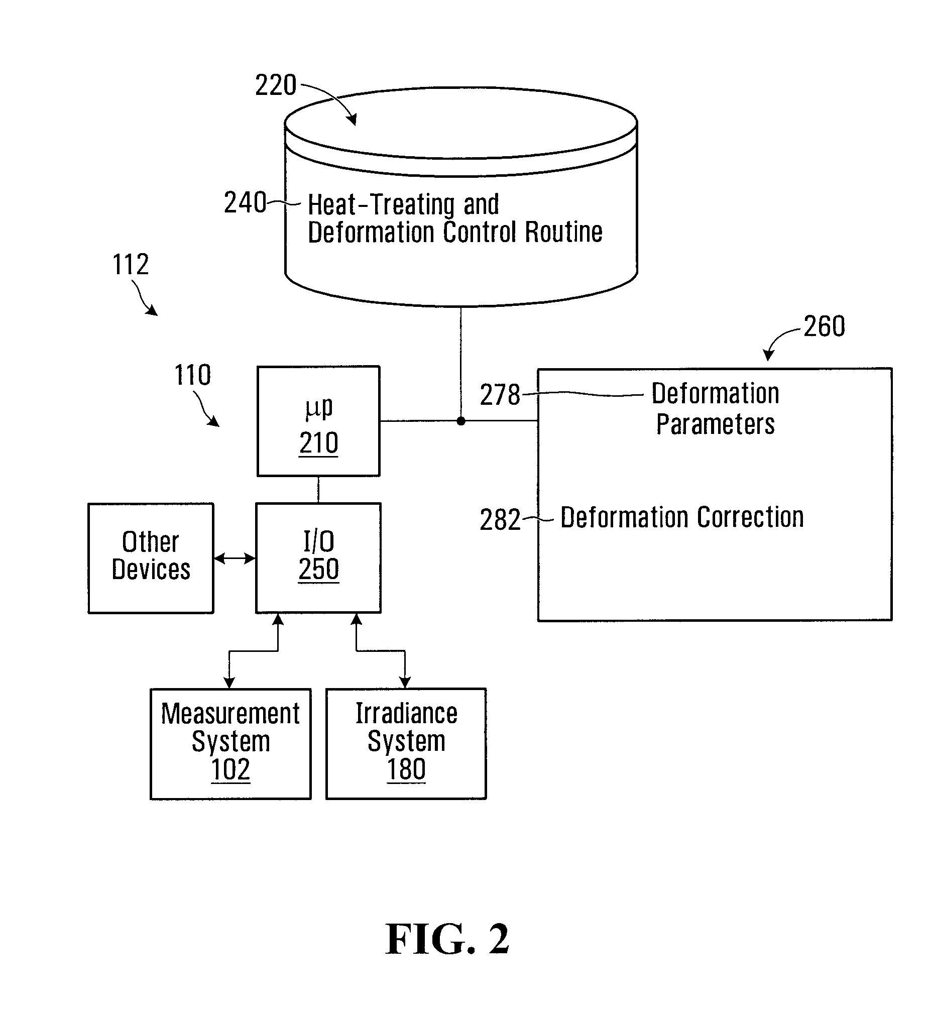
[0057]Referring to FIG. 1, an apparatus for heat-treating a workpiece according to a first embodiment of the invention is shown generally at 100. In this embodiment, the apparatus 100 includes a heat-treating system configured to heat-treat a workpiece 106, a measuring system configured to measure deformation of the workpiece during heat-treating of the workpiece by the heat-treating system, and a processor circuit 110. The processor circuit 110 is configured to cooperate with the heat-treating system and the measuring system to cause an action to be taken in relation to the heat-treating of the workpiece, in response to the measuring system measuring the deformation of the workpiece.

[0058]In this embodiment, the heat-treating system includes a backside heating system 150 and a topside heating system 180, described in greater detail below.

[0059]Also in this embodiment, the measuring system includes a plurality of measurement devices, such as those shown at 160, 162, 164 and 102, for...


PUM


Abstract

Methods and apparatus for heat-treating a workpiece are disclosed. An illustrative method includes measuring deformation of a workpiece during heat-treating thereof, and taking an action in relation to the heat-treating of the workpiece, in response to the measuring of the deformation of the workpiece. The workpiece may include a semiconductor wafer. Taking an action may include applying a deformation correction to a temperature or reflectivity measurement of the wafer during thermal processing, or may include modifying the heat-treating of the wafer, for example.

Description

CROSS-REFERENCE TO RELATED APPLICATIONS[0001]This application claims the benefit of priority from U.S. Patent Application No. 61 / 071,764 filed on May 16, 2008.FIELD OF THE INVENTION[0002]The present invention relates to methods and apparatus for heat-treating a workpiece, such as a semiconductor wafer, for example.BACKGROUND[0003]Numerous applications involve heat-treating a workpiece. For example, in the manufacture of semiconductor chips such as microprocessors, the workpiece typically includes a semiconductor wafer, supported in a thermal processing chamber for annealing or other heat-treating purposes. Commonly owned U.S. Pat. No. 7,501,607, which is hereby incorporated herein by reference, discusses examples of heat-treating techniques for annealing such semiconductor wafers, in which the wafer is first pre-heated to an intermediate temperature, following which the top or device side surface is rapidly heated to an annealing temperature. The initial pre-heating stage occurs at ...

Claims


Application Information

Patent Timeline
Patent Type & Authority Applications(United States)
IPC IPC(8): H01L21/66H05B1/00
CPCC21D11/00H01L21/324H01L21/67098H01L21/67115H01L21/67248H01L2924/0002H01L22/12H01L22/26H01L21/67253H01L2924/00
Inventor CAMM, DAVID MALCOLMCIBERE, JOSEPHSTUART, GREGMCCOY, STEVE
Owner MATTSON TECHNOLOGY
Why Eureka
Try Eureka