Method for installing a dome-shaped pressure bulkhead in a rear section of an aircraft, and device for carrying out the method

a technology for rear sections and bulkheads, which is applied in the direction of manufacturing tools, transportation and packaging, and efficient propulsion technologies, can solve the problems of difficult access to the interior of the tail section, and achieve the effect of simple manufacturing engineering terms

Inactive Publication Date: 2011-07-28
AIRBUS OPERATIONS GMBH
View PDF34 Cites 18 Cited by
  • Summary
  • Abstract
  • Description
  • Claims
  • Application Information

AI Technical Summary

Benefits of technology

[0007]The object of the invention is to provide a method which is simple in manufacturing engineering terms and which allows a pressure bulkhead to be integrated into a prefabricated, already cured, one-piece tail section for a pressure-tight aircraft fuselage cell with tolerance compensation. A further object of the invention is to provide a device for implementing the method.
[0015]In step b), the tail section prepared thus is introduced by the lifting means into a swivel frame inside a joining station. The swivel frame and thus the tail section are initially still in a horizontal position. Further drilling operations, for example, can be carried out in this horizontal position. To be mentioned in this connection is, for example, the very precise introduction of holes into the rudder unit metal fittings which were attached in step a). The drilling means inside the joining station is preferably configured as a gantry drilling means which is arranged displaceably above the swivel frame or alternatively below the swivel frame. The gantry drilling means is preferably guided on at least two mutually parallel rails and can be positioned with great accuracy. The gantry drilling means makes it possible to position a drilling tool with great accuracy in all three spatial directions. The tail section in the joining station is then brought into a vertical position by the swivel frame so that a connection region or a connection cross section of the tail section to which the pressure bulkhead is connected is directed upwards, while an end portion of the conical tail section usually with significantly smaller cross-sectional dimensions is directed downwards. The swivel frame can also be configured such that a rotation of the tail section about the longitudinal axis is also possible.
[0016]As a result of the horizontal assembly position of the pressure bulkhead, on the one hand the assembly process is simplified, since the working height is always independent of the respective peripheral position of the joining operations to be carried out on the tail section. Furthermore, an inherent deformation, caused by gravity, of the cross-sectional shape of the tail section is avoided and the pressure bulkhead which is preferably configured to be self-centring can easily be inserted and positioned in a “floating” manner inside the connection region of the tail section.
[0024]This annular former construction area can be disposed externally or alternatively can also be arranged inside the device used for implementing the method. An internal arrangement of the annular former construction area in particular provides a further increase in efficiency when the method is implemented, since a high temporal parallelisation of the production process is achieved at the same time as short transportation distances. The integration of the annular former is preferably concluded at the latest at the time when the fuselage section is transferred from the horizontal pre-assembly position in the horizontal placement area into the swivel frame inside the joining station and is sufficiently prepared for the integration of the pressure bulkhead.
[0027]This measure also provides a high temporal parallelisation of the method and thus a short processing time of the tail section up until the complete integration of the pressure bulkhead. During the attachment of the edge angle, the pressure bulkhead is in a horizontal position in a suitable supporting device corresponding to the annular former.
[0036]During the operating sequence according to the method, the fuselage section is transferred by a suitable lifting means from the pre-assembly area into the swivel frame of the joining station. The lifting means which can be configured, for example, as a conventional overhead crane makes it possible to freely position the tail section spatially, the pre-assembly area, the joining station, the pressure bulkhead construction area and the annular former construction area being located inside the region covered by the lifting means. According to the invention, the swivel frame allows the fuselage section to swivel about a transverse axis into a vertical position to facilitate the assembly of the pressure bulkhead on the connection region of the tail section. Furthermore, the swivel frame can be configured such that it is also possible for the tail section to pivot about its longitudinal axis (i.e. parallel to the longitudinal axis of the aircraft). The device preferably has in each case at least three pre-assembly areas, three joining areas, three annular former construction areas and three pressure bulkhead construction areas in order to achieve a sufficiently short processing time by temporal parallelisation when the pressure bulkhead is integrated. However, the provision of only one lifting means and one gantry drilling means inside the entire assembly device is usually sufficient, whereas each pre-assembly area is preferably equipped at least with one automatic drilling and riveting means.

Problems solved by technology

Furthermore, it is conceivable for further working steps to be carried out on the tail section, for example pre-finishing operations with the necessary line systems or the like, because when the dome-shaped pressure bulkhead has been integrated it is difficult to access the interior of the tail section.

Method used


Image

  • Method for installing a dome-shaped pressure bulkhead in a rear section of an aircraft, and device for carrying out the method
  • Method for installing a dome-shaped pressure bulkhead in a rear section of an aircraft, and device for carrying out the method
  • Method for installing a dome-shaped pressure bulkhead in a rear section of an aircraft, and device for carrying out the method

Examples


Embodiment Construction

[0043]In the drawings, like constructional components have like reference numerals in each case.

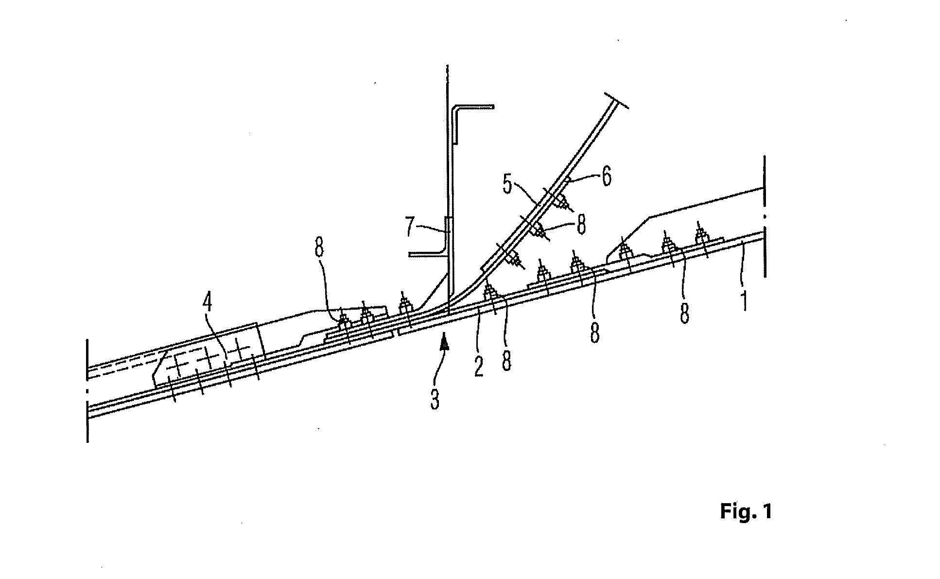
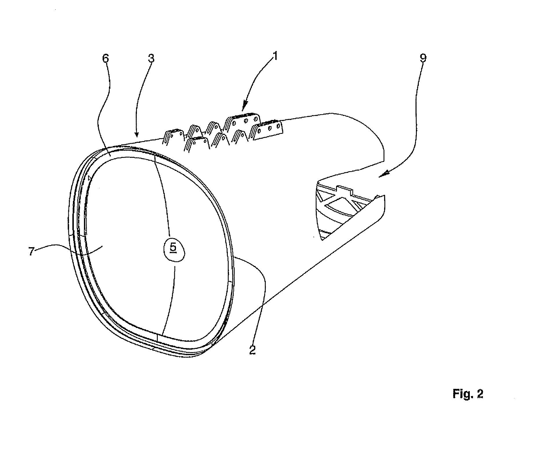
[0044]FIG. 1 is a sectional view through a connection region of a tail section with a further fuselage section added on.

[0045]A tail section 1 is provided with a circumferential transverse butt strap 2 which forms a connection region 3 for attaching a further fuselage section 4. The connection region 3 can, in principle, have any curved shape which is optionally also locally variable, but is preferably at least circular, elliptic and / or oval in portions. A substantially dome-shaped pressure bulkhead 5 is provided with a circumferential edge angle 6. The actual connection between the fuselage section 4 and the tail section 1 is formed by the transverse butt strap 2. Positioned on the transverse butt strap 2 are the edge angle 6 of the pressure bulkhead 5 and an annular former 7 which, while cooperating, ensure the mechanical connection of the pressure bulkhead 5 in the connection region 3 ...


PUM

PropertyMeasurementUnit
angleaaaaaaaaaa
pressureaaaaaaaaaa
areaaaaaaaaaaa

Abstract

The invention relates to a method for installing an especially dome-shaped pressure bulkhead on a one-piece, substantially conical rear section for an aircraft, wherein said rear section comprises a connection area and an end area, comprising the steps:a) horizontally accommodating a prefabricated rear section in a horizontal support,b) inserting the rear section into a pivoting frame,c) pivoting the rear section into a vertical position using the pivoting frame, wherein the connection area of the rear section points upward,d) horizontally placing and centering the pressure bulkhead on the connection area, ande) joining of the pressure bulkhead with the rear section in the area of the connection area.The invention further relates to an apparatus for carrying out the method using a pivoting frame for tilting the rear section into a vertical position for installing the pressure bulkhead.

Description

CROSS-REFERENCE TO RELATED APPLICATIONS[0001]This application is a continuation of PCT / EP2009 / 057812 filed Jun. 23, 2009 and claims the benefit of U.S. Provisional Application No. 61 / 134,141, filed Jul. 7, 2008 and German Patent Application No. 10 2008 040 213.3, filed Jul. 7, 2008, the entire disclosures of which are herein incorporated by reference.FIELD OF THE INVENTION[0002]The invention relates to a method for assembling an in particular dome-shaped pressure bulkhead on a one-piece, substantially conical tail section of an aircraft, the tail section having a connection region and an end region.[0003]The invention also relates to a device for implementing the method.[0004]Nowadays, tail sections of aircraft are usually produced with at least two shells. In order to achieve the required pressure tightness of the aircraft fuselage cell, the tail sections are closed rearwards by a pressure bulkhead which in most cases is dome-shaped. In conventional shell construction, the tail sec...

Claims


Application Information

Patent Timeline
Patent Type & Authority Applications(United States)
IPC IPC(8): B23P23/04B23P11/00
CPCB21J15/14B23P2700/01B64C1/068B64C1/10Y10T29/49826B64F5/0009Y02T50/433B64C1/069Y10T29/53417B64C2001/0072B64F5/10Y10T29/53974Y10T29/53961Y10T29/49966Y10T29/49895Y10T29/53913Y02T50/40B64C1/0685
Inventor WEBER, FRANKSCHOENFELDT, OLAF
Owner AIRBUS OPERATIONS GMBH
Why Eureka
Try Eureka