Mass Spectrometer

a mass spectrometer and mass separator technology, applied in the field of mass spectrometers, can solve problems such as system loss of ions, and achieve the effects of increasing the axial energy of ions, increasing the amplitude of mass, and altering the character of the low-mass cut o

Active Publication Date: 2011-07-28
MICROMASS UK LTD
View PDF45 Cites 17 Cited by
  • Summary
  • Abstract
  • Description
  • Claims
  • Application Information

AI Technical Summary

Benefits of technology

[0176]Ions may be driven progressively over a pseudo-potential barrier in decreasing order of their mass to charge ratio by progressively increasing the amplitude of the one or more transient DC voltage or potentials which is applied to the electrodes of the ion guide and / or by decreasing the effective amplitude of the pseudo-potential barrier. The amplitude of the pseudo-potential barrier may be decreased by reducing the amplitude of the applied RF voltage and / or by increasing the frequency of the applied RF voltage.
[0177]According to another embodiment the pseudo-potential barrier may be augmented by an additional DC potential applied to electrodes in proximity to the pseudo-potential barrier. According to this embodiment the amplitude of the barrier is a combination of a mass to charge ratio dependent pseudo-potential barrier and a mass to charge ratio independent DC potential barrier. The amplitude of the effective barrier may be decreased by reducing the amplitude of the RF voltage and / or by increasing the applied frequency of the applied RF voltage and / or by reducing the amplitude of the applied DC potential. Ions, which are mass selectively ejected from the ion guide in an axial manner may be transmitted onwardly for further processing and / or analysis.
[0178]According to another embodiment the pseudo-potential barrier may be arranged at the entrance of the ion guide such that if ions having a particular mass to charge ratio have sufficient axial energy then they will overcome the pseudo-potential barrier and so enter the preferred ion guide. If ions having a particular mass to charge ratio have insufficient axial energy to overcome the pseudo-potential barrier then they are preferably prevented from entering the ion guide and hence are lost to the system. The preferred ion guide may be used to affect a low-mass cut off characteristic. The characteristics of this low-mass cut off may be altered by increasing the amplitude of the mass to charge ratio dependent barrier and / or by increasing the axial energy of the ions entering the ion guide.
[0179]According to a particularly preferred embodiment a first AC or RF voltage may be applied to the electrodes so that axially adjacent electrodes are maintained at opposite phases of the first AC or RF voltage. The polarity of a pair of electrodes may then be switched or reversed. At an instance in time the polarity of a plurality of electrodes may therefore be changed from +−+−+−+− to +−++−−+−. As a result the effective thickness of electrodes along a portion or section of the ion guide is effectively increased.

Problems solved by technology

Therefore, disadvantageously, if the oscillating electric field along the axis of the ion guide is changed in any way then this may cause undesired radial instabilities and / or resonance effects which may result in ions being lost to the system.

Method used


Image

  • Mass Spectrometer
  • Mass Spectrometer
  • Mass Spectrometer

Examples


Embodiment Construction

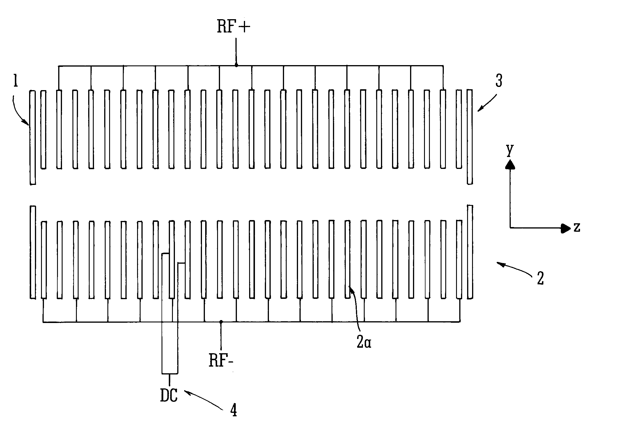
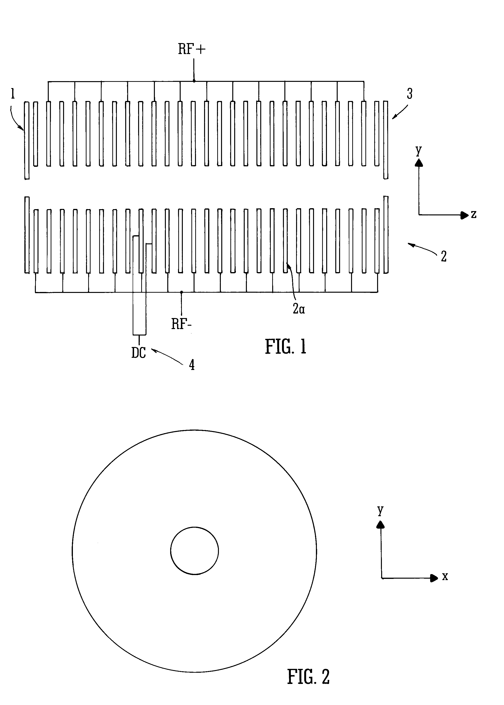
[0223]An embodiment of the present invention will now be described with reference to FIG. 1. According to this embodiment a RF ring stack ion guide 2 is provided. The ion guide preferably comprises an entrance plate or electrode 1 which is preferably held or maintained in use at a DC potential and a plurality of other annular electrodes or plates 2a. Opposite phases of a modulated (RF) potential are preferably applied to alternate electrodes or plates 2a which form the ion guide. The ion guide 2 preferably comprises an exit plate or electrode 3 which is preferably held or maintained in use at a DC potential.

[0224]According to the preferred embodiment an additional transient DC potential 4 is preferably applied to one or more of the ring electrodes 2a as shown. The transient DC potential 4 is preferably applied to one or more electrodes 2a at the same time for a relatively short period of time. The DC potential 4 is then preferably switched or applied to one or more adjacent or subse...


PUM


Abstract

An ion guide or mass analyser is disclosed comprising a plurality of electrodes having apertures through which ions are transmitted in use. A pseudo-potential barrier is created at the exit of the ion guide or mass analyser. The amplitude or depth of the pseudo-potential barrier is inversely proportional to the mass to charge ratio of an ion. One or more transient DC voltages are applied to the electrodes of the ion guide or mass analyser in order to urge ions along the length of the ion guides or mass analyser. The amplitude of the transient DC voltage applied to the electrode may be increased with time so that ions are caused to be emitted from the ion guide or mass analyser in reverse order of their mass to charge ratio.

Description

CROSS-REFERENCE TO RELATED APPLICATION[0001]This application is a continuation of U.S. patent application Ser. No. 12 / 297,481 filed on Jan. 23, 2009 which represents a National Stage of International Application No. PCT / GB2007 / 001589 filed on Apr. 30, 2007 and claims the benefit of U.S. Provisional Patent Application Ser. No. 60 / 801,772 filed on May 19, 2006. The entire contents of these applications are incorporated by reference.BACKGROUND OF THE INVENTION[0002]The present invention relates to a mass spectrometer and a method of mass spectrometry.[0003]It is a common requirement in a mass spectrometer for ions to be transferred through a region maintained at an intermediate pressure i.e. at a pressure wherein collisions between ions and gas molecules are likely to occur as ions transit through an ion guide. Ions may need to be transported, for example, from an ionisation region which is maintained at a relatively high pressure to a mass analyser which is maintained at a relatively ...

Claims


Application Information

Patent Timeline
Patent Type & Authority Applications(United States)
IPC IPC(8): H01J49/28H01J3/26
CPCH01J49/065H01J49/4235H01J49/062Y10T436/24H01J49/36H01J49/0031H01J49/022
Inventor GREEN, MARTINWILDGOOSE, JASON LEEPRINGLE, STEVEN DEREKKENNY, DANIEL JAMES
Owner MICROMASS UK LTD
Why Eureka
Try Eureka