

Phosphor, phosphor manufacturing method, and white light emitting device
a technology of phosphor and manufacturing method, applied in the direction of luminescent compositions, energy-saving lighting, sustainable buildings, etc., can solve the problems of reduced optical efficiency due to re-radiation efficiency, difficult to realize superior color rendering, and insufficient green and red color components to display unnatural colors
- Summary
- Abstract
- Description
- Claims
- Application Information
AI Technical Summary
Benefits of technology
Problems solved by technology
Method used
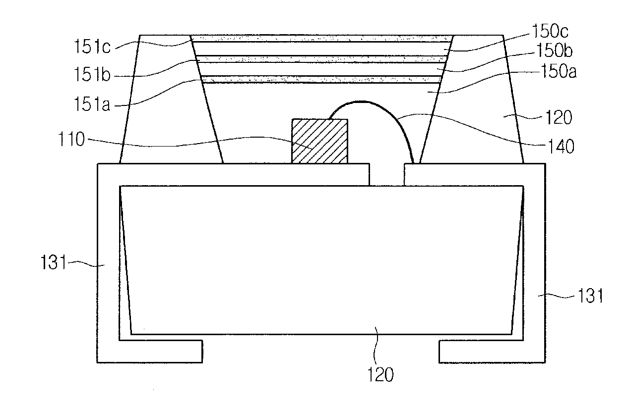
Image

Examples
first embodiment
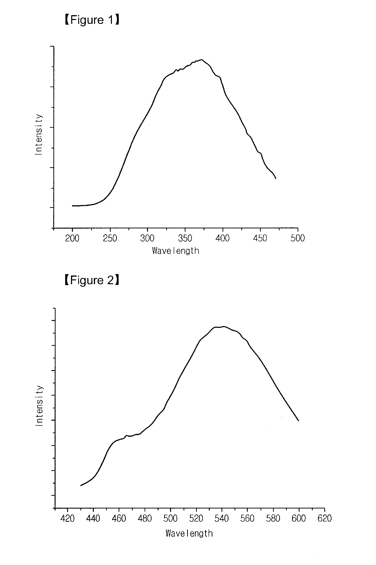
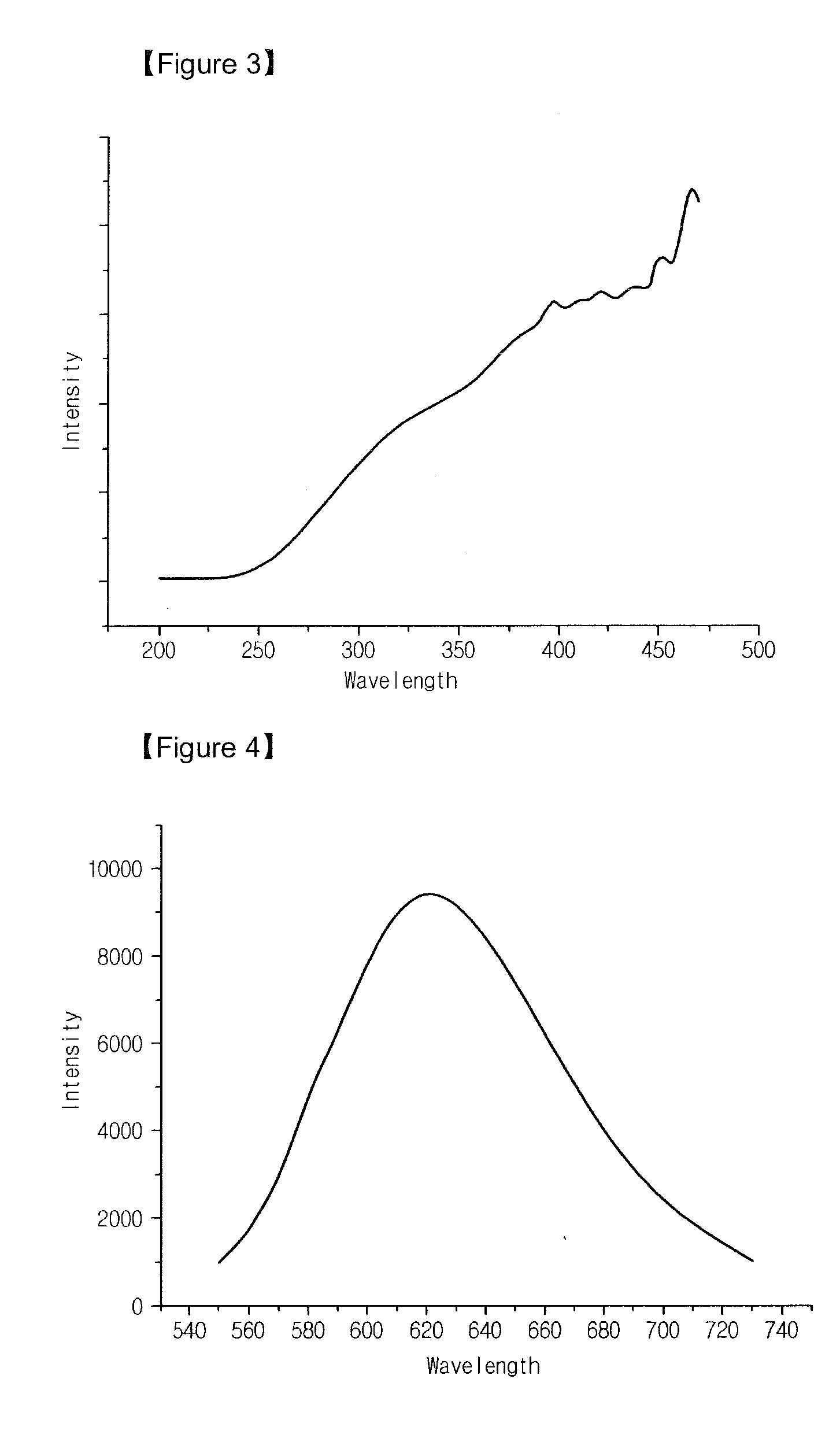
[0073]According to a first embodiment, provided is a phosphor emitting light having a peak wavelength in a wavelength band of about 480 nm to about 680 nm using light having a peak wavelength in a wavelength band of about 350 nm to about 480 nm as an excitation source. Here, the phosphor uses inorganic compounds of an aMO-bAl2O3-cSi3N4 three-component system as a main component. Furthermore, M is one kind or two kinds of elements selected from a group consisting of Mg, Ca, Sr, and Ba (0.2≦a / (a+b)≦0.9, 0.05≦b / (b+c)≦0.85, and 0.4≦c / (c+a)≦0.9).
[0074]The phosphor according to the first embodiment has a stable crystal structure. In addition, although the phosphor is exposed to an excitation source for a long time or used for a long time, luminance reduction of the phosphor may be minimized.
[0075]The phosphor according to the first embodiment includes a Sr3AlSi2O9 / 2N8 / 3:Eu phosphor, a Sr2AlSi3O7 / 2N4:Eu2 phosphor, a Sr2Al3Si2O13 / 2N8 / 3:Eu2 phosphor, and a Sr2Al3SiO13 / 2N4 / 3:Eu2 phosphor. Alt...
second embodiment
[0130]According to a second embodiment, provided is a phosphor emitting light having a peak wavelength in a wavelength band of about 480 nm to about 680 nm using light having a peak wavelength in a wavelength band of about 350 nm to about 480 nm as an excitation source. Here, the phosphor is formed of a composition having an aMO-bAlN-cSi3N4 three-component system as a main component. Furthermore, M is one selected from alkaline earth metals and uses a composition satisfying conditions of 0.2≦a / (a+b)≦0.9, 0.05≦b / (b+c)≦0.85, 0.4≦c / (c+a)≦0.9 as a mother material.
[0131]The phosphor according to the second embodiment may be manufactured to emit light having a peak wavelength in a desired wavelength band among wavelength bands of the green color, yellow color, and red color.
[0132]According to the phosphor disclosed in the second embodiment, a SrAlSi3ON5:Eu phosphor uses a light source, which emits the light having the peak wavelength in the wavelength band of about 350 nm to about 480 nm,...
example 1
SrAlSi3ON5:Eu Manufacture
[0157]Process 1. Green Phosphor Manufacture
[0158]SrCO3, Si3N4, AlN, Eu2O3 used as source salts are quantified to oxidation-treat the source salts at a temperature of about 800° C. to about 1,200° C. for a time period of about 2 hours. Then, the oxidation-treated source salts are put into a ball mill container to ball-mill the source salts for a time period of about 2 hours to about 24 hours using acetone as a solvent, and then to dry the ball-milled source salts. Thereafter, the dried source salts are sintered at a temperature of about 1,300° C. for a time period of about 4 hours to about 10 hours under a reducing atmosphere in which a supply velocity of a hydrogen / nitrogen gas (95:5 v / v) is controlled at a flow rate of about 100 sccm to 300 sccm to manufacture a SrAlSi3ON5:Eu green phosphor. Here, europium (Eu) contains about 0 mole % by weight to about 50 mole % by weight.
[0159]Process 2. Yellow Phosphor Manufacture
[0160]After the SrAlSi3ON5:Eu green phosp...
PUM
 Abstract
Description
Claims
Application Information