Single-Particle LIDAR Anemometry Method and System

a single-particle, lidar anemometry technology, applied in the direction of speed/acceleration/shock measurement, fluid speed measurement, instruments, etc., can solve the problem of heterogeneous gas illuminated by laser beams, and achieve good bijection and reduce power/sensitivity requirements

Active Publication Date: 2011-07-28
THALES SA
View PDF2 Cites 10 Cited by
  • Summary
  • Abstract
  • Description
  • Claims
  • Application Information

AI Technical Summary

Benefits of technology

[0024]The single-particle anemometry system may be carried by an aircraft in order to measure its airspeed, the emitted light beam being advantageously directed at an angle of illumination of between 30° and 70° to the velocity vector of the aircraft. To determine a three-dimensional velocity vector, a 3D-coordinate system may be chosen with all the axes positioned according to the same velocity-axis angle. Beyond the three non-coplanar axes there is redundancy, and therefore the possibility of performing measurement integrity tests.
[0025]The light beam may be focused close to the fuselage of the aircraft, at a distance of between 10 cm and several metres therefrom. This distance is chosen to be far beyond the “boundary layer” so as to have a good bijection between observables and estimated parameters but is also chosen to be as close as possible, so as to reduce power / sensitivity requirements.

Problems solved by technology

Furthermore, the gas illuminated by the laser beam may be heterogeneous.

Method used


Image

  • Single-Particle LIDAR Anemometry Method and System
  • Single-Particle LIDAR Anemometry Method and System
  • Single-Particle LIDAR Anemometry Method and System

Examples


Embodiment Construction

[0041]With regard to clarity, the same references in the various figures denote the same elements.

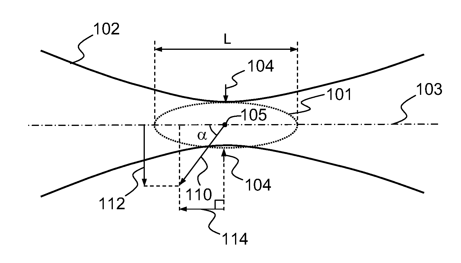
[0042]FIG. 1 shows a longitudinal cross section of a LIDAR light beam. In the example, particles of which it is desired to measure the velocity are spheroids having an average diameter of the order of 0.1 μm. These particles have the advantage of moving at substantially the same speed as the gas in which they are suspended, due to their small size.

[0043]The beam envelope 102 is shown in the figure. The focal volume 101 of the beam extends from one side of the beam waist 104 to the other. By way of example, the waist is approximately 50 μm wide and the width L of the beam focal volume 101 along the optical axis 103 is less than 5 mm (Rayleigh zone), which corresponds to a volume 101. The optical axis 103 is directed, for example, so as to make an angle α of 60° with the displacement direction of the particles of which it is desired to measure the velocity. Thus, the velocity vector 110 o...


PUM


Abstract

The present invention concerns a single-particle LIDAR anemometry method and system comprising the continuous emission of one or more light beams through a gas containing particles, said beam being focused onto a measurement volume, a step of detecting a signal backscattered by particles passing through said volume, the method being characterized in that it comprises at least the following phases:
    • determining in a time period Δt the frequency of each of the pulses included in the backscattered signal;
    • distinguishing pulses based on duration and/or intensity and/or frequency-modulation criteria; and
    • estimating the displacement velocity of said beam relative to the gas from several of the frequencies determined over the time period Δt excluding those corresponding to the pulses distinguished during the preceding step
A notable application of the invention is for the measurement of the airspeed of an aircraft

Description

CROSS-REFERENCE TO RELATED APPLICATIONS[0001]This application claims priority to foreign France patent application No. 0903660, filed on Jul. 24, 2009, the disclosure of which is hereby incorporated by reference in its entirety.FIELD OF THE INVENTION[0002]The present invention concerns a single-particle LIDAR anemometry method and system. Its application notably is to the measurement of the airspeed of an aircraft.BACKGROUND OF THE INVENTION[0003]Laser anemometry notably allows the determination of the displacement velocity of a gas, for example a flow of air around an aircraft, by exploiting the presence of suspended aerosols. These aerosols, also termed particles or tracers are for example dust particles or droplets. An optical beam is emitted by a laser and backscattered by aerosols suspended in the air, then the measurement of the frequency shift between an optical reference signal and the backscattered signal allows the velocity of the carrier relative to the aerosols, and thus...

Claims


Application Information

Patent Timeline
Patent Type & Authority Applications(United States)
IPC IPC(8): G01P3/36
CPCG01N15/1434G01N15/1459G01S17/58G01P5/26G01S7/493G01N2015/1075
Inventor RENARD, ALAINLACONDEMINE, XAVIERSCHLOTTERBECK, JEAN-PIERRE
Owner THALES SA
Why Eureka
Try Eureka