Gain calibration of a digital controlled oscillator

a digital controlled oscillator and gain technology, applied in the field of data communication, can solve the problems of a slow time constant of 200 ms, the cost of additional circuitry amounting to approximately 13 of the pll, and the technique is mostly analog in natur

Active Publication Date: 2006-02-16
TEXAS INSTR INC
View PDF1 Cites 116 Cited by
  • Summary
  • Abstract
  • Description
  • Claims
  • Application Information

AI Technical Summary

Benefits of technology

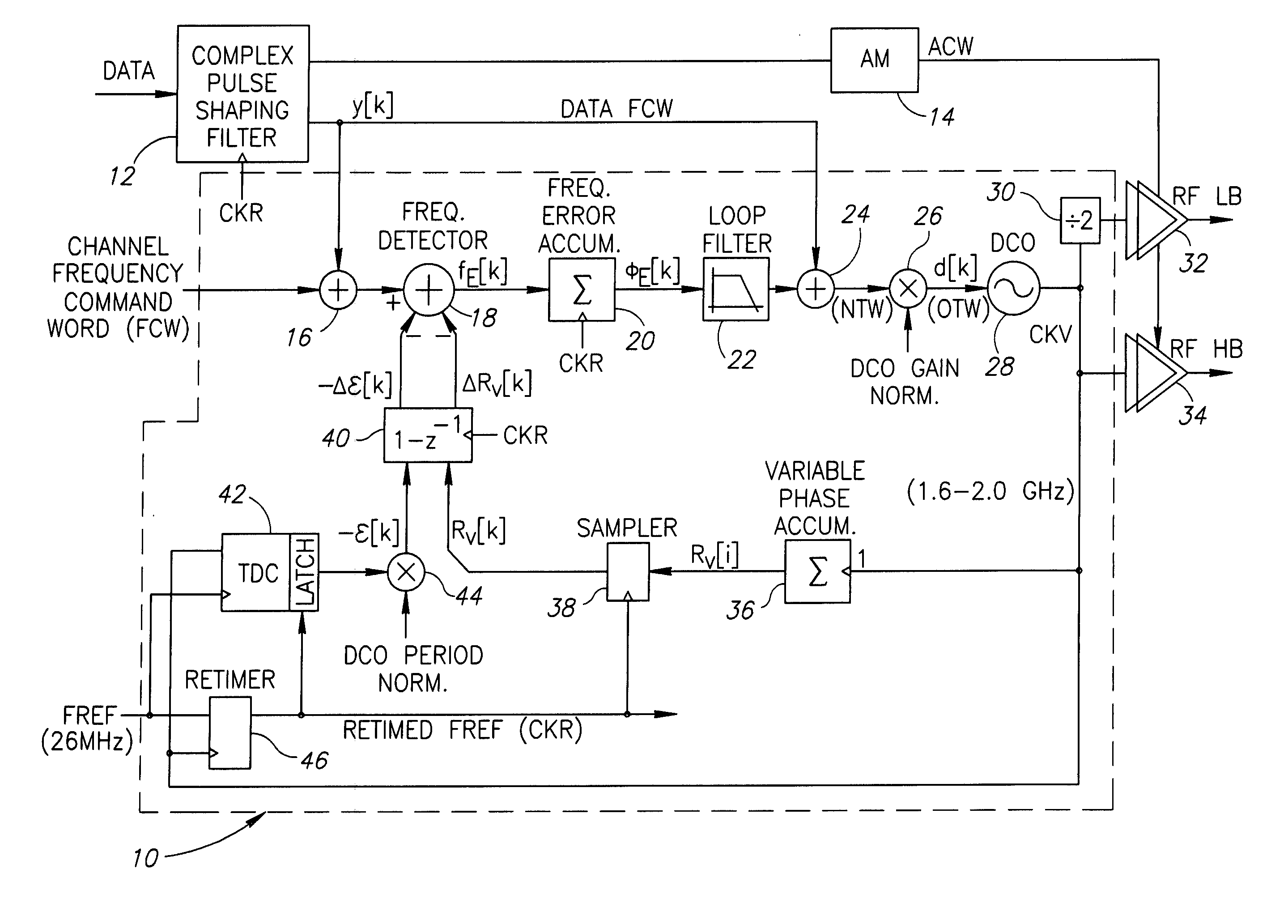
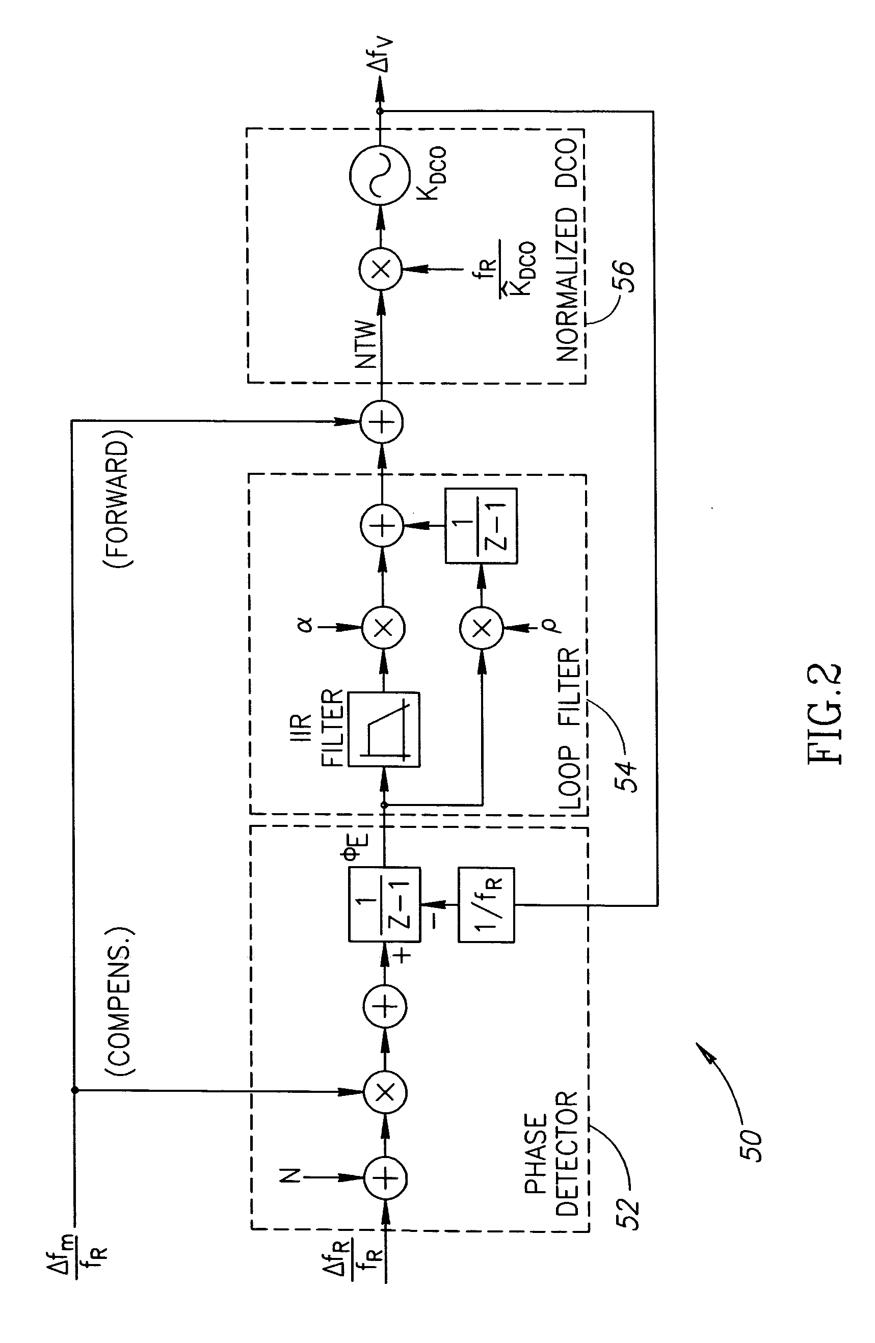
[0009] The present invention is a novel apparatus for and a method of estimating, calibrating and tracking in real-time the gain of a radio frequency (RF) digitally controlled oscillator (DCO) in an all-digital phase locked loop (ADPLL). The precise setting of the inverse DCO gain in the ADPLL modulating path allows direct wideband frequency modulation that is independent of the ADPLL loop bandwidth. The gain calibration technique is based on a steepest descent iterative algorithm wherein the ADPLL phase error is sampled and correlated with the modulating data to generate a gradient. Other well known variants of LMS, such as sign-sign or sign-error may be employed with similar effect. The gradient is then scaled and added to the current value of the DCO gain multiplier. This process, repeated over time, results in an improved estimate of the true DCO gain that ensures optimum performance and allows continuous operation in the presence of possible sources of variability, such as temperature changes.

Problems solved by technology

Unfortunately, the PLL frequency response is subject to process, voltage and temperature (PVT) variations of the charge pump, loop filter and voltage controlled oscillator (VCO).
A disadvantage of this technique, however, is the cost of additional circuitry amounting to approximately ⅓ of the PLL, including a reference error filter, DPLL, vector test and RF phase quantizer.
Further, this technique suffers from a slow time constant of 200 ms.
A disadvantage of this approach, however, is that it is mostly analog in nature and requires precise calibration of the oscillator and other PLL analog components.
The prior art techniques discussed hereinabove suffer from disadvantages such as they (1) require a dedicated time for background calibration, which makes them suitable only for packetized operations, such as GSM / EDGE, but not WCDMA, (2) require dedicated and expensive hardware, (3) are dc based and are thus sensitive to frequency drift of the oscillator, or (4) require factory calibration.

Method used


Image

  • Gain calibration of a digital controlled oscillator
  • Gain calibration of a digital controlled oscillator
  • Gain calibration of a digital controlled oscillator

Examples


Embodiment Construction

[0039]

Notation Used ThroughoutThe following notation is used throughout this document.TermDefinitionADPLLAll Digital Phase Locked LoopASICApplication Specific Integrated CircuitCDMACode Division Multiple AccessCKRRetimed Reference ClockCKVVariable Oscillator ClockCMOSComplementary Metal Oxide SemiconductorDCODigitally Controlled OscillatorDECTDigital Enhanced Cordless TelecommunicationsDRPDigital RF Processor or Digital Radio ProcessorEDGEEnhanced Data rates for GSM EvolutionFCWFrequency Command WordFPGAField Programmable Gate ArrayFREFFrequency ReferenceGFSKGaussian Frequency Shift KeyingGSMGlobal System for Mobile CommunicationsHBHigh BandHDLHardware Description LanguageICIntegrated CircuitLBLow BandLMSLeast Mean SquaresLPFLow Pass FilterMOSCAPMetal Oxide Semiconductor CapacitorPLLPhase Locked LoopPVTProcess, Voltage, TemperatureRFRadio FrequencyRMSRoot Mean SquareTDCTime to Digital ConverterUMTSUniversal Mobile Telecommunications SystemVCOVoltage Controlled OscillatorWCDMAWideban...


PUM


Abstract

A novel apparatus for and a method of estimating, calibrating and tracking in real-time the gain of a radio frequency (RF) digitally controlled oscillator (DCO) in an all-digital phase locked loop (ADPLL). Precise setting of the inverse DCO gain in the ADPLL modulating path allows direct wideband frequency modulation that is independent of the ADPLL loop bandwidth. The gain calibration technique is based on a steepest descent iterative algorithm wherein the phase ADPLL error is sampled and correlated with the modulating data to generate a gradient. The gradient is then scaled and added to the current value of the DCO gain multiplier.

Description

REFERENCE TO RELATED APPLICATION [0001] This application claims priority to U.S. Provisional Application Ser. No. 60 / 601,374, filed Aug. 12, 2004, entitled “New LMS-Based KDCO Algorithm”, incorporated herein by reference in its entirety.FIELD OF THE INVENTION [0002] The present invention relates to the field of data communications and more particularly relates to an apparatus for and method of LMS-based gain calibration technique for a radio frequency (RF) digitally controlled oscillator (DCO) in an all digital phase locked loop (ADPLL). BACKGROUND OF THE INVENTION [0003] Oscillators are a key component in the design of radio frequency (RF) communication systems. [0004] The estimation and calibration of the modulation gain of an RF oscillator is currently an area of active research. Accurate knowledge of this gain significantly reduces the complexity and increases the performance of the transmit frequency modulation path. It is particularly beneficial in systems implemented in deep ...

Claims


Application Information

Patent Timeline
Patent Type & Authority Applications(United States)
IPC IPC(8): H03L7/00
CPCH03L7/085H03L2207/50H03L7/0991
Inventor STASZEWSKI, ROBERT B.FEYGIN, GENNADYELIEZER, OREN E.LEIPOLD, DIRK
Owner TEXAS INSTR INC
Why Eureka
Try Eureka