
Producing ageing gas for exhaust gas after-treatment systems

Inactive Publication Date: 2011-07-28
FEV
View PDF3 Cites 10 Cited by
  • Summary
  • Abstract
  • Description
  • Claims
  • Application Information

AI Technical Summary

Benefits of technology

[0021]The combustion air ratio can be varied in predetermined cycles in accordance with the test regulations. In this way, the exhaust gas after-treatment device can be provided with different ageing gas compositions and ageing gas temperatures in accordance with the load spectrum such as it corresponds to mixed operational conditions. By adjusting the parameters of the combustion air ratio as well as fuel quantities and air quantities, the exhaust gas after-treatment device can be subjected to cyclical thermal loads and thus experiences conditions such as they occur under actual driving conditions.
[0027]Furthermore, it is advantageous to vary also the supplied combustion air quantity in order to adapt same to the changed quantity of injected fuel without allowing excessive effects on the swirl. It is therefore proposed that the external secondary air flow can be throttled.
[0030]In order to avoid any disadvantageous effect on the ageing gas temperature, the primary ageing gas return flow is also reduced when the secondary air flow is throttled.
[0037]Oil and / or fuels and / or foreign gas and / or air, such as, age-related, they occur in the course of engine combustion with increasing wear, can be added in front of the catalyst to the ageing gas of the secondary and / or tertiary exhaust gas return flow or to the exhaust gas, the advantage being the reproducibility of said process stages when producing the ageing gas as a function of time, i.e. as a function of the cycles of the production of ageing gas.
[0038]The inventive process is particularly advantageous in that it is possible to simulate the overrun fuel cut-off of an internal combustion engine in that the fuel supply to the burner is interrupted and that, to re-start the combustion chamber, there is set a combustion air ratio of λ<1 (rich fuel mixture) in combination of a very high swirl rate of the primary air flow, which results in very good ignition conditions, so that the cut-off phases can be observed in a very controlled way. Also, with the objective of reducing the mass flow, exhaust gas can be guided through the catalyst in the bypass. To control the mass flows, it is possible to use suitable exhaust gas flaps. In addition, it is possible to age a plurality of catalysts in parallel and to control the mass flows by suitable exhaust gas flaps. Furthermore, if exhaust gas manifolds are provided, the temperature of the individual partial mass flows can be set by a measured exhaust gas return and / or by individual exhaust gas flaps.Ageing Process

Problems solved by technology

As a result of the reduction in the size of the active surface it is no longer possible for all emissions to be oxidised and reduced, so that the emissions behind the catalyst, which are released into the environment, increase.
At temperatures of 1400° C. and more the ceramic member melts, which leads to total destruction.
This is normally indicated by a performance loss of the engine due to too high an exhaust gas pressure in the catalyst.
On the one hand, the active surface can be poisoned chemically by foreign substances, for example fuel or oil additives, which chemical poisoning, as a result of chemical reactions, partially destroys or reduces the catalytic surface.
In addition, there occurs mechanical poisoning wherein the active layer is covered for example by lead and sulphur from fuel and oil, which also leads to the reduction of the catalytic surface.
The older the catalyst, the lower its storage capacity.
It is possible to simulate the process of ageing exhaust gas after-treatment systems, more particularly exhaust gas catalysts, on engine test rigs, but on the one hand it is expensive and on the other hand it is difficult to reproduce because engine ageing influences represent an influencing factor which cannot be calculated.
Producing said swirl plates is expensive, with optimum combustion being possible at only one single operating point of the burner, whereas the ageing cycles require several operating conditions because the ageing gas has to be provided with different temperatures and, optionally, also has to be produced with different combustion air conditions.

Method used


Image

  • Producing ageing gas for exhaust gas after-treatment systems
  • Producing ageing gas for exhaust gas after-treatment systems
  • Producing ageing gas for exhaust gas after-treatment systems

Examples


Embodiment Construction

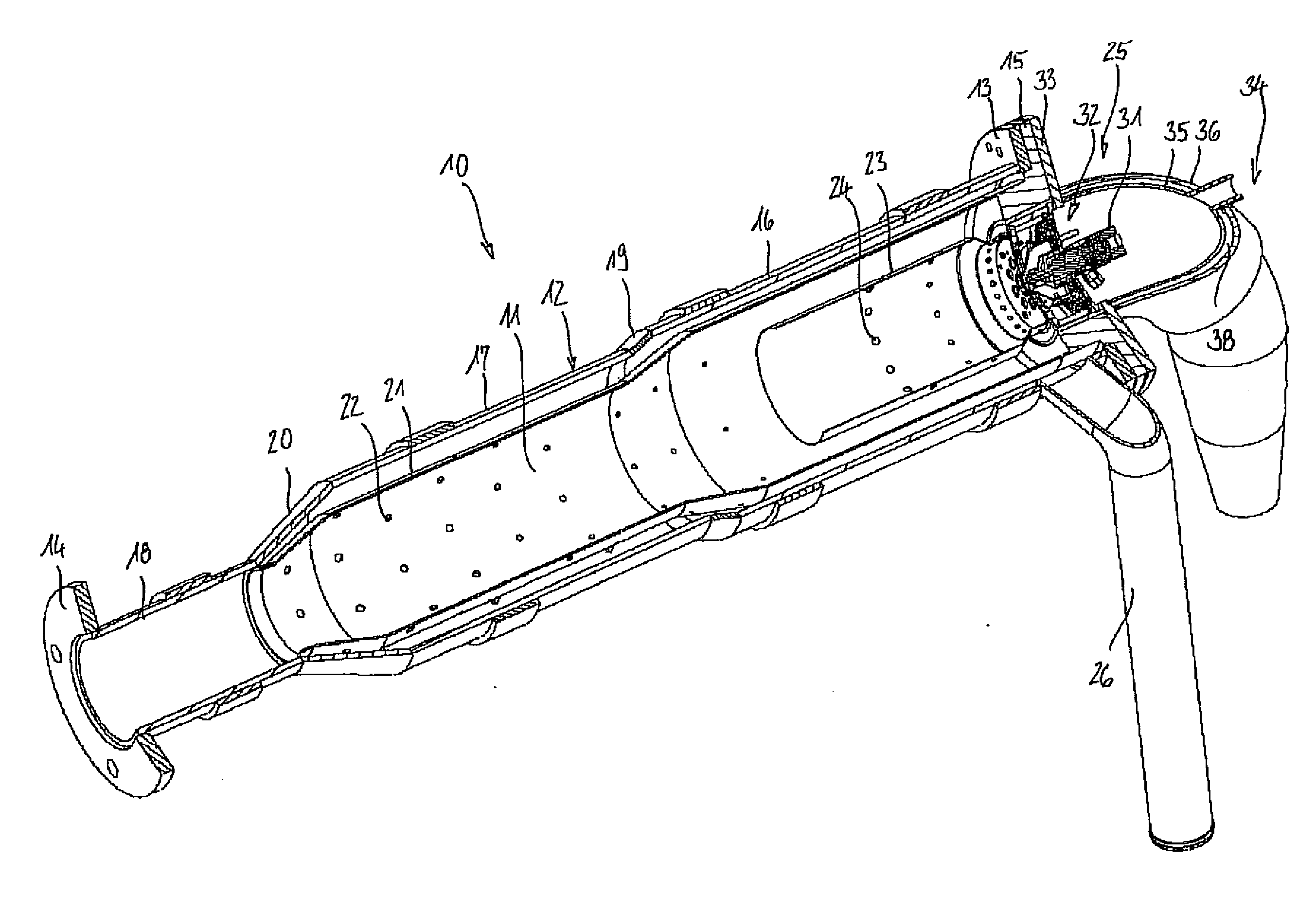
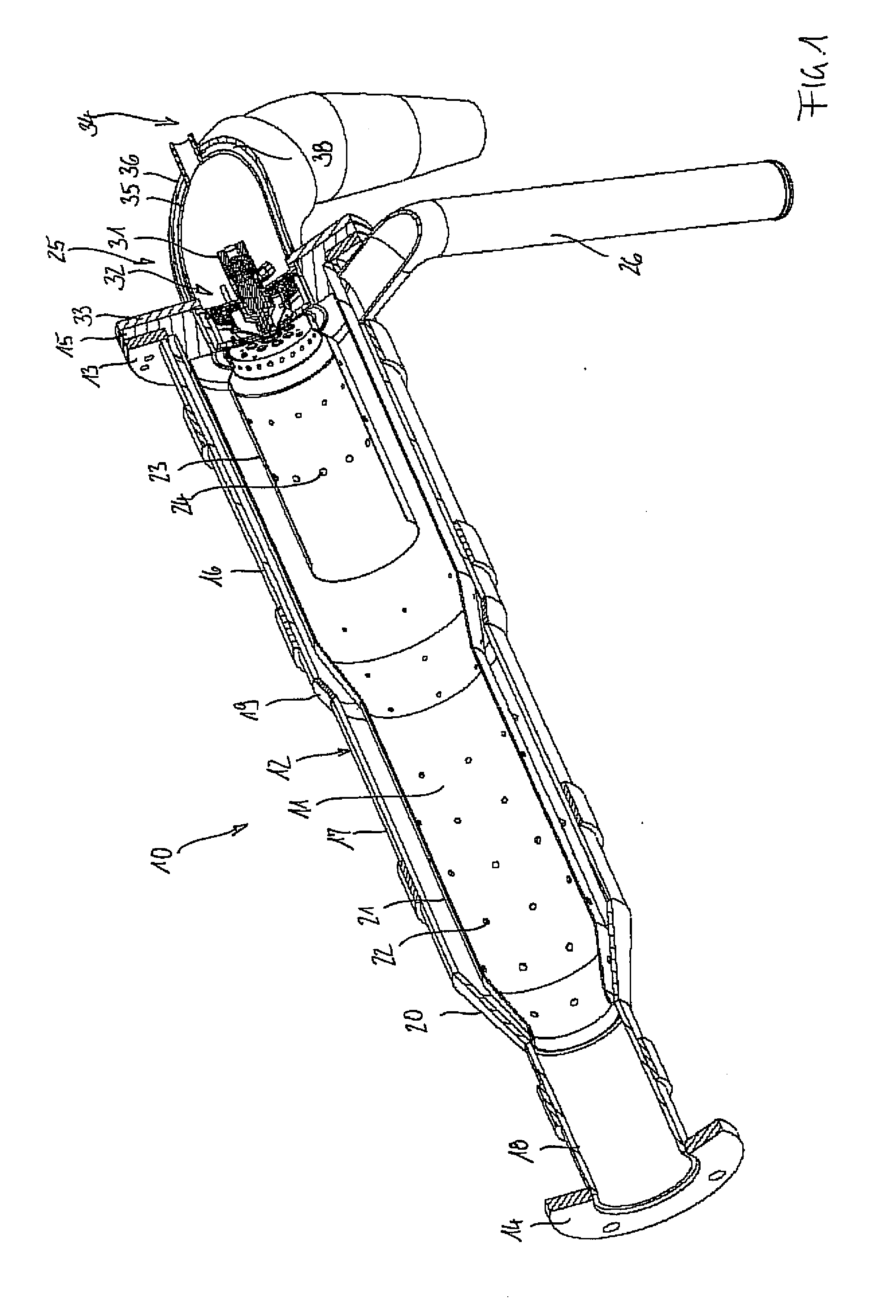
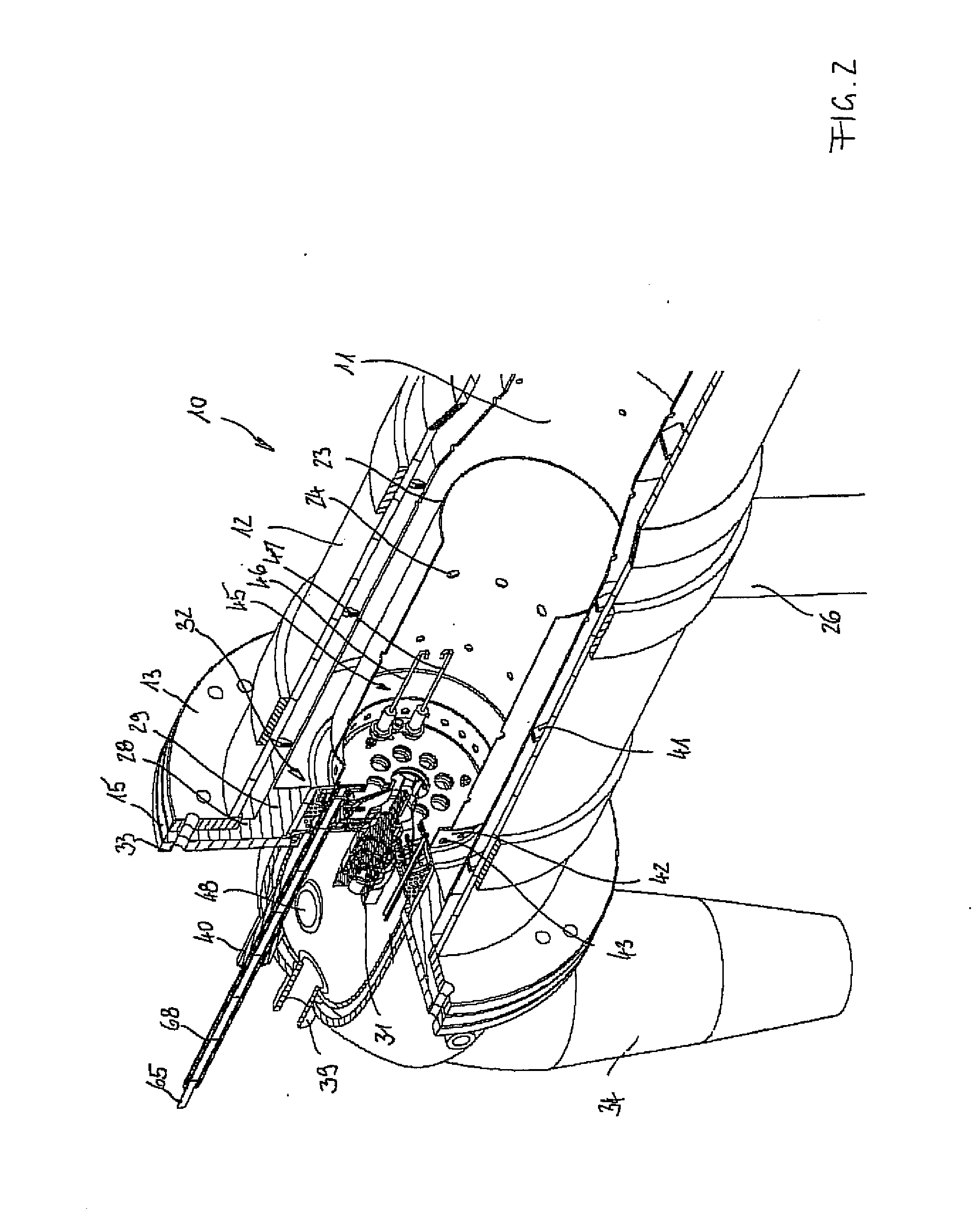
[0068]FIG. 1 shows an inventive burner 10 with a combustion chamber 11, which burner 10 comprises an outer rotationally symmetric burner sheath 12 which extends between an entry flange 1 and an exit flange 14 and comprises three length portions 16, 17, 18 whose diameter decreases from the entry flange to the exit flange and which are connected to one another via conical transition portions 19, 20. A carrier flange 15 which comprises an outer collar and an inner annular projection to be described in greater detail with reference to the following Figures is threaded to the entry flange 13. The collar centres the entry flange 13 to which there is attached the burner sheath 12. On its outside, the inner annular projection at the carrier flange 15 carries a mixing pipe 21 for returning conditioned ageing gas and extends, at a radial distance, along the length of the first two portions 16, 17 of the burner sheath 12 and of the two conical transition portions 19, 20. From the transition po...


PUM


Abstract

The invention relates to a process of producing ageing gas for ageing components for the after-treatment of exhaust gas in a burner which comprises a combustion chamber with at least one fuel injection nozzle and with a combustion gas supply system with means for generating swirl, wherein the swirl of the combustion air is set as a function of the selected combustion air ratio λ.

Description

FIELD OF THE INVENTION[0001]The present invention is related to a process for producing ageing gas, and in particular for producing ageing gas for ageing components related to an after-treatment of exhaust gas.BACKGROUND OF THE INVENTION[0002]Motor vehicles with internal combustion engines are subject to emission laws which, nowadays, can only be complied with by using exhaust gas after-treatment systems which adjoin, and are connected to, the internal combustion engines in the exhaust gas line. The exhaust gas after-treatment systems have to have the service life which is specified by law. For the European Union, after the introduction of exhaust gas stage EURO 4, there is specified a durability in the form of a minimum driving performance of 100,000 km, whereas after the introduction of exhaust gas stage EURO 5, a durability in the form of a minimum driving performance of 160,000 km has been specified. For homologizing a vehicle (type approval), it is necessary to prove permanent ...

Claims


Application Information

Patent Timeline
IPC IPC(8): F23L7/00F23D14/62
CPCF01N3/025F01N3/2033F01N11/00F01N2240/14F01N2550/02F01N2550/04Y02T10/47F23C7/008F23D11/408F23D2900/11402F23D2900/14481F23N2037/12Y02T10/26F01N2550/20F23N2237/12Y02T10/12Y02T10/40
Inventor BAHN, MICHAEL
Owner FEV
Learn More