Soi semiconductor device comprising substrate diodes having a topography tolerant contact structure

a contact structure, topography-tolerant technology, applied in semiconductor devices, diodes, electrical devices, etc., can solve the problems of affecting the performance of the corresponding substrate window, causing a plurality of problems, and significant yield losses, so as to reduce the height level, avoid the effect of electrical leakage paths, and increase the lateral distan

Active Publication Date: 2011-08-04
TAIWAN SEMICON MFG CO LTD
View PDF5 Cites 8 Cited by
  • Summary
  • Abstract
  • Description
  • Claims
  • Application Information

AI Technical Summary

Benefits of technology

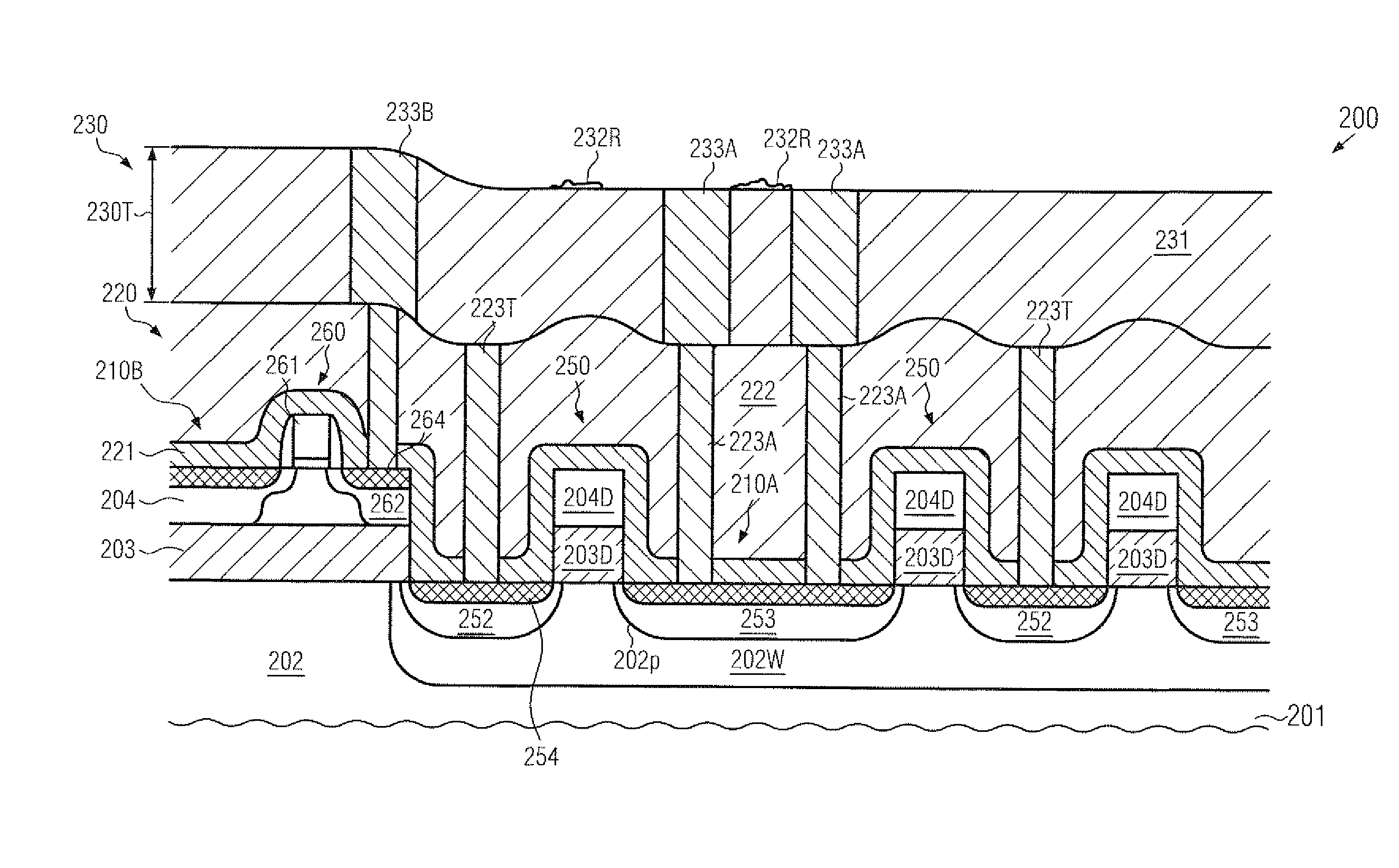
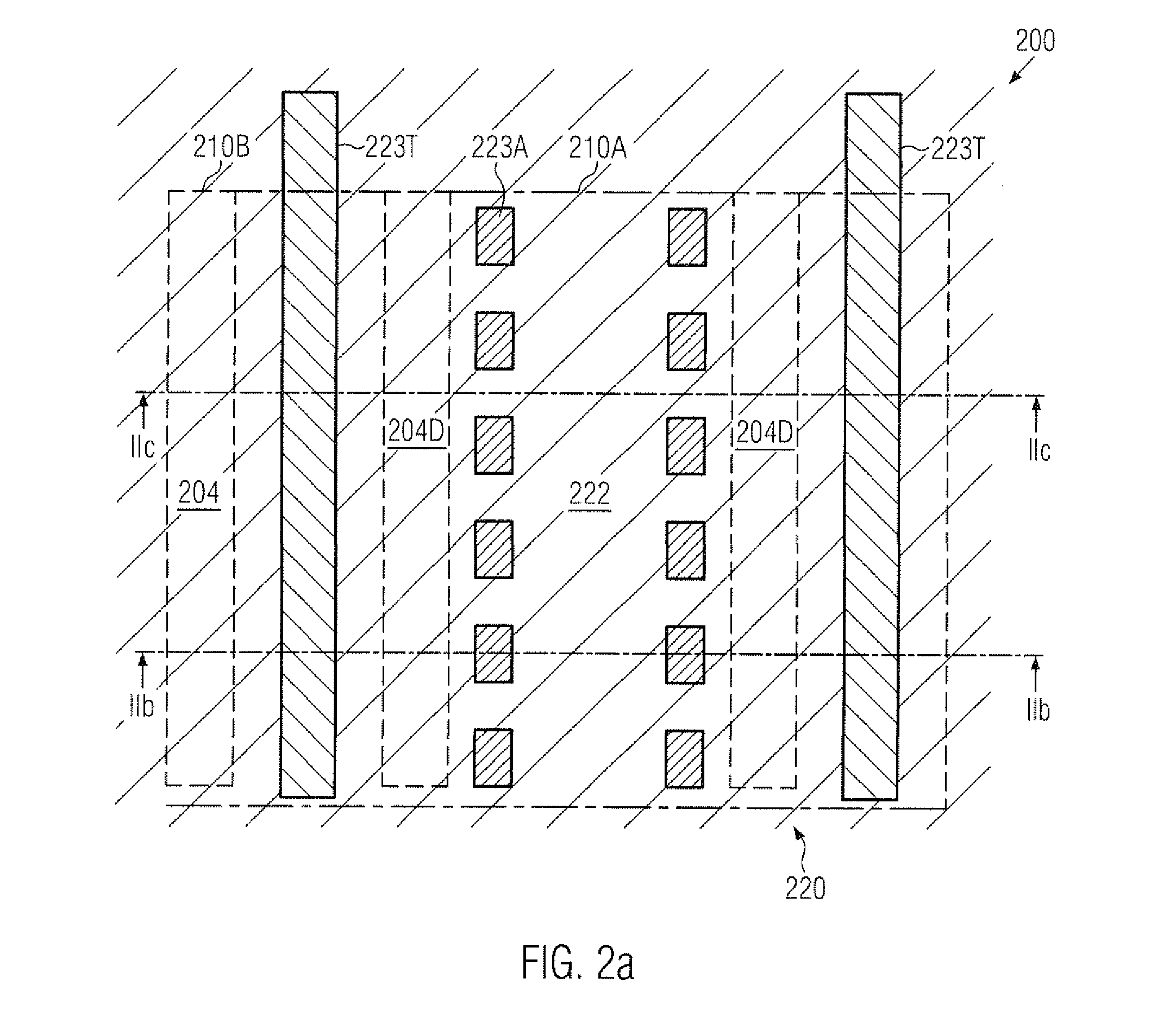
[0015]Generally, the present disclosure provides semiconductor devices in which substrate diodes may be efficiently formed in the crystalline substrate material of the semiconductor device, such as an SOI device, wherein the resulting surface topography, i.e., the difference in height level between a device area comprising transistor elements and a substrate diode area or substrate window, may not negatively affect performance of the substrate diodes when forming sophisticated contact and metallization levels. To this end, the geometric arrangement, i.e., the design and the corresponding implementation in actual semiconductor devices, may be appropriately adjusted such that any metal residues that may remain in the metallization layer upon removing any excess material, for instance by CMP and the like, may not negatively affect the overall performance in the substrate diode area. That is, the substrate diode area may be reconfigured such that metal lines may be formed within the area of the substrate diodes which are electrically connected exclusively to one type of diode electrodes, i.e., either the cathodes or the anodes, so that any possible leakage paths created during the formation of the metallization layer may not affect the overall electrical performance of the substrate diodes. On the other hand, the other type of diode electrodes may be connected to metal lines provided with increased lateral distance with respect to any metal lines positioned in the critical area of reduced height level, thereby reliably avoiding any electrical leakage paths between cathodes and anodes of the substrate diodes provided within the substrate diode area. In some illustrative aspects disclosed herein, the connection of one type of diode electrodes may be accomplished within the contact level by providing appropriately configured contact elements in the form of local interconnects, which may then be connected to the metallization level with the desired lateral distance so as to avoid any leakage paths within the metallization layer. Consequently, sophisticated semiconductor devices may be formed on the basis of design requirements selected in accordance with electrical performance rather than providing a less pronounced surface topography, while at the same time the probability of creating leakage paths between anodes and cathodes of the substrate diode may be significantly reduced without requiring additional process steps.

Problems solved by technology

This configuration provides significant advantages, but also gives rise to a plurality of issues.
For example, one important issue in high performance devices, such as microprocessors and the like, is an efficient device internal temperature management due to the significant heat generation of the transistors.
Conventional approaches for forming substrate diodes may result in significant yield losses and, thus, loss of performance in the corresponding substrate window due to the continuous shrinkage of device features, such as transistors, lines and the like.
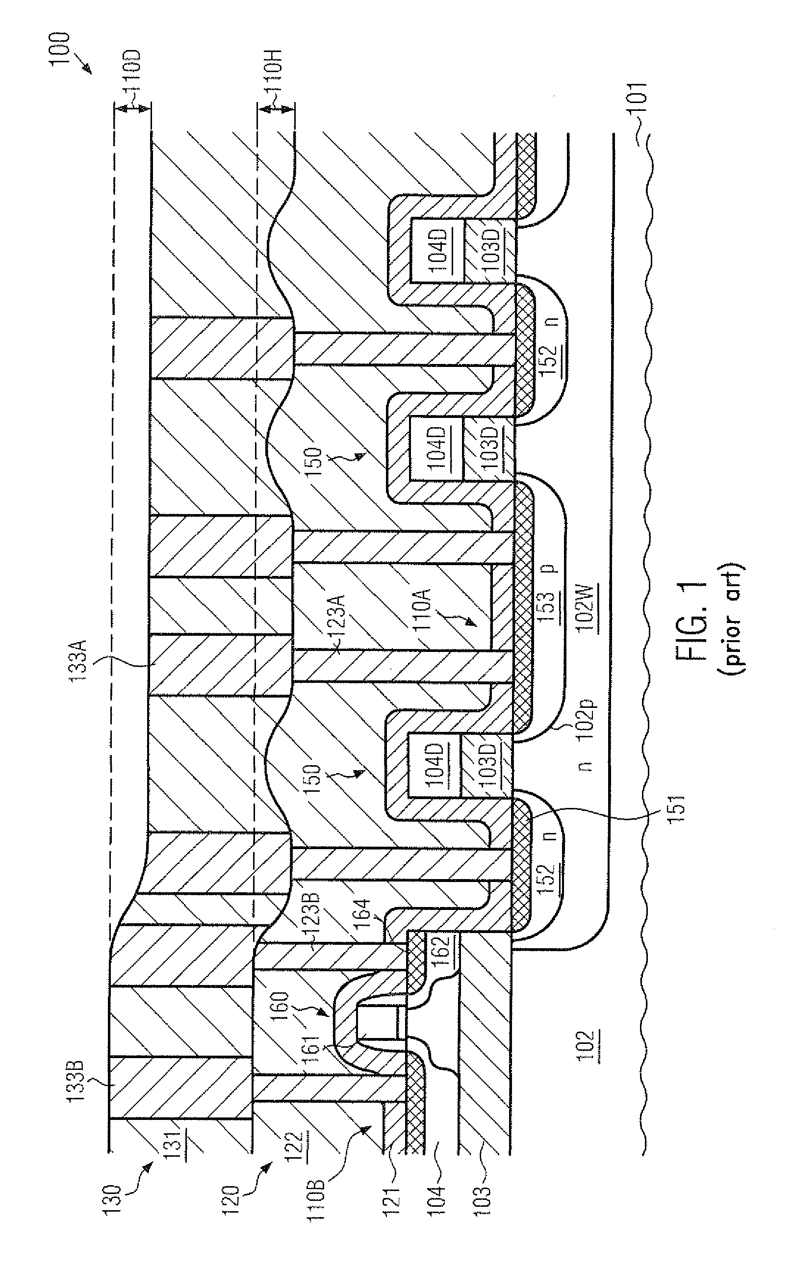
In particular, many material removal processes based on a polishing process have been identified to cause significant irregularities when forming contact elements and metallization layers, as will be described in more detail with reference to FIG. 1.
The pronounced surface topography caused by this difference in height levels, in turn, may result in significant irregularities in the further processing of the device 100.
In this case, leakage paths or short circuits between metal lines 133A may be created, thereby at least reducing performance of the substrate diodes 150 or causing a complete failure of one of these devices.
Since reliable temperature data may strongly depend on the diode characteristics, a reduction in the reliability or a degradation of performance of the substrate diodes may contribute to significant yield losses and / or reduced functionality of the semiconductor device 100.

Method used


Image

  • Soi semiconductor device comprising substrate diodes having a topography tolerant contact structure
  • Soi semiconductor device comprising substrate diodes having a topography tolerant contact structure
  • Soi semiconductor device comprising substrate diodes having a topography tolerant contact structure

Examples


Embodiment Construction

[0026]Various illustrative embodiments of the invention are described below. In the interest of clarity, not all features of an actual implementation are described in this specification. It will of course be appreciated that in the development of any such actual embodiment, numerous implementation-specific decisions must be made to achieve the developers' specific goals, such as compliance with system-related and business-related constraints, which will vary from one implementation to another. Moreover, it will be appreciated that such a development effort might be complex and time-consuming, but would nevertheless be a routine undertaking for those of ordinary skill in the art having the benefit of this disclosure.

[0027]The present subject matter will now be described with reference to the attached figures. Various structures, systems and devices are schematically depicted in the drawings for purposes of explanation only and so as to not obscure the present disclosure with details ...


PUM


Abstract

In an SOI semiconductor device, substrate diodes may be formed on the basis of a superior design of the contact level and the metallization layer, thereby avoiding the presence of metal lines connecting to both diode electrodes in the critical substrate diode area. To this end, contact trenches may be provided so as to locally connect one type of diode electrodes within the contact level. Consequently, additional process steps for planarizing the surface topography upon forming the contact level may be avoided.

Description

BACKGROUND OF THE INVENTION[0001]1. Field of the Invention[0002]Generally, the present disclosure relates to integrated circuits, and, more particularly, to SOI semiconductor devices comprising semiconductor elements, such as substrate diodes, that are formed in the crystalline material of the substrate.[0003]2. Description of the Related Art[0004]The fabrication of integrated circuits requires a large number of circuit elements, such as transistors and the like, to be formed on a given chip area according to a specified circuit layout. Generally, a plurality of process technologies are currently practiced, wherein, for complex circuitry, such as microprocessors, storage chips, ASICs (application specific ICs) and the like, CMOS technology is one of the most promising approaches due to the superior characteristics in view of operating speed and / or power consumption and / or cost efficiency. During the fabrication of complex integrated circuits using CMOS technology, millions of comple...

Claims


Application Information

Patent Timeline
Patent Type & Authority Applications(United States)
IPC IPC(8): H01L27/12
CPCH01L27/0207H01L29/8611H01L27/1207H01L27/0629
Inventor HEINRICH, JENSFROHBERG, KAIRUTTLOFF, KERSTIN
Owner TAIWAN SEMICON MFG CO LTD
Why Eureka
Try Eureka