
Emergency power supply apparatus

a technology of emergency power supply and power supply device, which is applied in the direction of emergency power supply arrangement, transportation and packaging, sustainable buildings, etc., can solve the problems of unreliable and excessively expensive maintenance, unreliable and unreliable solution, and difficulty in powering the essential elements, etc., to achieve the effect of prolonging the runtime power

Active Publication Date: 2011-08-04
LEANECO APS
View PDF13 Cites 105 Cited by
  • Summary
  • Abstract
  • Description
  • Claims
  • Application Information

AI Technical Summary

Benefits of technology

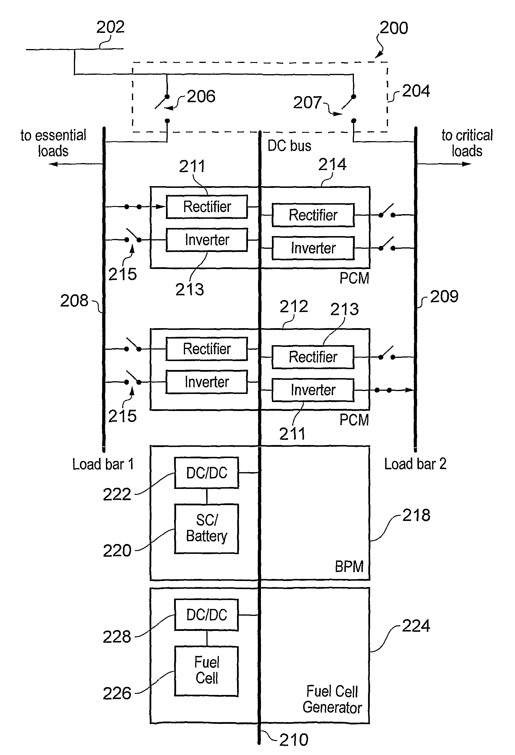
[0027]urgent (minimal break) AC feed, in which when the primary power source is active power is fed from it directly to the destination, but when the primary power source is inactive power is fed from the DC bus to the destination. The switch unit may be arranged to disconnect the primary power source from all of the load bar when the primary power source is inactive. If the inactivity is a “brown out”, i.e. the primary power source is operating outside of its nominal voltage or frequency window, the switch unit may be arranged to connect to a load bar that occupies solely the DC bus feed state, since power conversion modules in the rectifier state may still operate for the primary power source even though it may not deliver power in the right form for powering applications in the destination. This arrangement may increase runtime.
[0057]If the conventional UPS needs repair, the extended run generator may be reconfigured on-the-fly as a UPS. Thus, the controller may be arranged to reconfigure the power conversion means to cause the second load bar additionally to occupy the DC bus feed state and then the first load bar to occupy the critical (no break) state, to permit removal or testing of the uninterruptible power supply. In other words, the second load bar is arranged to feed the DC bus from the primary power source and the power conversion means is configured to deliver power from the DC bus to the first load bar. When the power transferable from the DC bus exceeds a predetermined level (i.e. the power capacity and availability switched into the first load bar from the DC bus is above a set threshold) the switch unit may disconnect the first load bar from the primary power source so that it receives power only from the DC bus. If there is a grid outage, a power transfer failure from the second load bar to the DC bus may cause the secondary power source to be activated. This may occur using the priority protocol outlined above. The DC bus voltage may thus not suffer a break in power supply and hence the first load bar may continue to supply power without a break.

Problems solved by technology

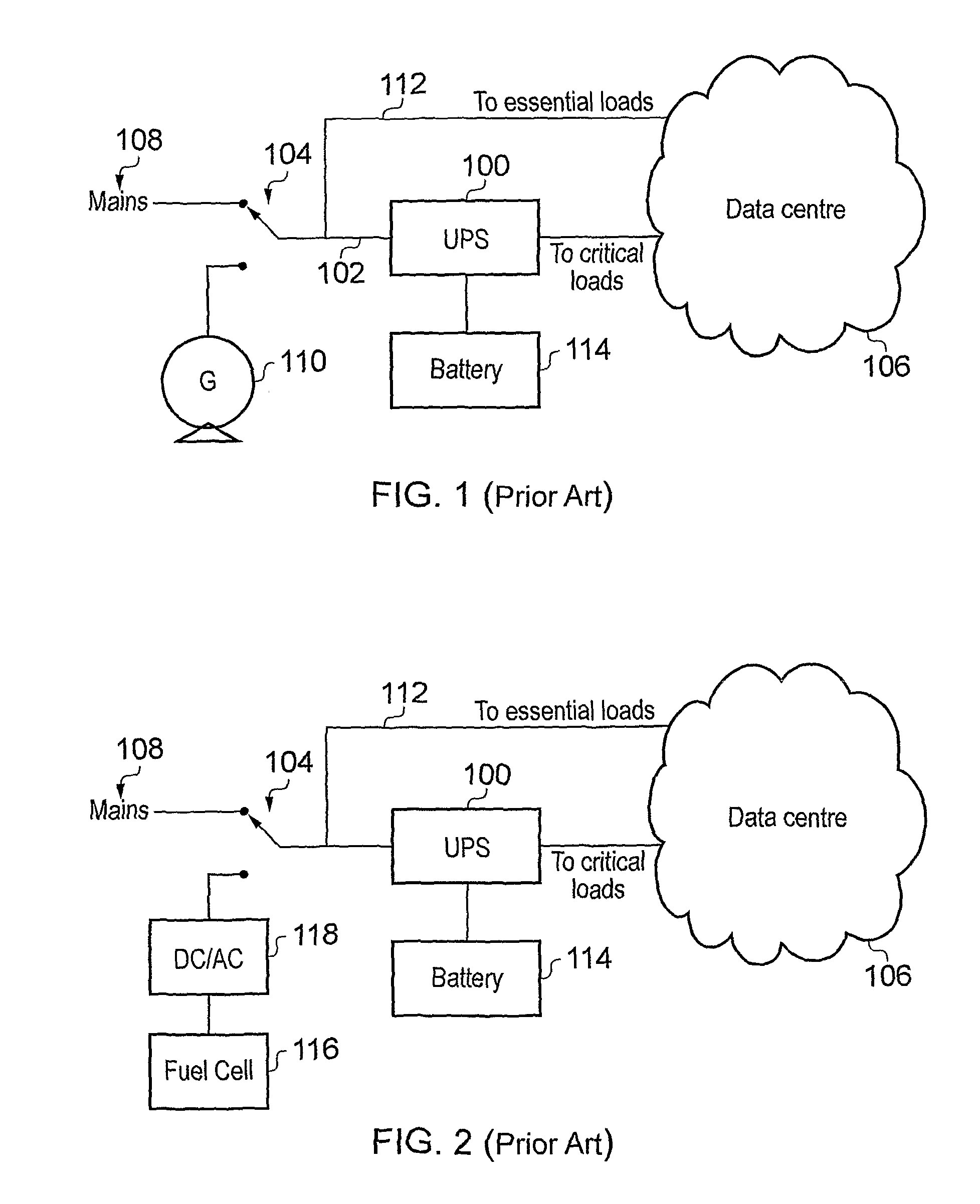
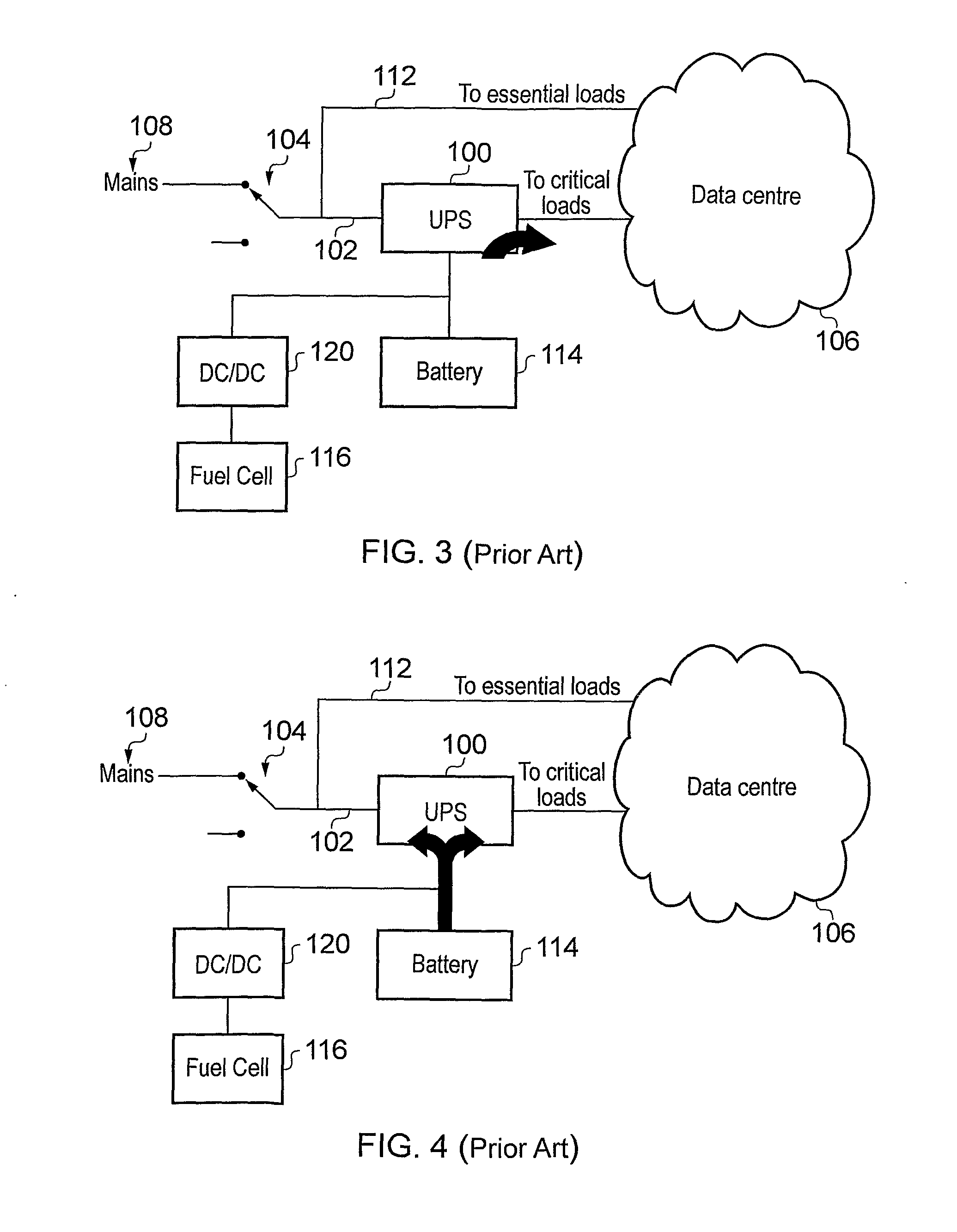
The time limit may arise if the UPS emergency power is sourced from a limited energy storage like re-chargeable batteries.
Increasing battery storage is simple but suffers from a number of drawbacks.
Firstly, above a certain power level the physical amount of batteries required can grow beyond any practical level, whereby the solution becomes unpractical, unreliable and excessively expensive to maintain.
Secondly, it can be difficult to power the essential elements because they are (by definition) not connected to the critical power line.
Firstly, diesel engines expose emission problems, noise and vibration.
Secondly, the installation can be complex, which makes the cost per kW very high, especially for small systems / low power.
However, in this system the essential loads are not supported.

Method used


Image

  • Emergency power supply apparatus
  • Emergency power supply apparatus
  • Emergency power supply apparatus

Examples


Embodiment Construction

; FURTHER OPTIONS AND PREFERENCES

[0078]FIG. 6 shows emergency power supply apparatus 200 that is a first embodiment of the invention. The apparatus comprises a master switch unit 204 connected to a primary power source 202, which may be mains power supply from a utility. The switch unit has a first switch 206 for selectively connecting the primary power source 202 to a first load bus 208 (load bar 1) and a second switch connected in parallel with the first switch 206 for selectively connecting the primary power source 202 to a second load bus 209 (load bar 2). The load buses 208, 209 (hereinafter load bars) may thus be individually connected to or disconnected from the primary power source by the switch unit 204. The master switch unit 204 may be a piece of dedicated apparatus (e.g. a plug-in module) as discussed in the embodiments below, or may be incorporated as part of a rack or backplane system in which the apparatus is installed.

[0079]The load bars 208, 209 may each be connecte...


PUM


Abstract

A modular emergency power system architecture (200) with a plurality of output power supply lines for feeding power to a destination, in which the operational status of each output power supply line is configurable. The architecture comprises a plurality of load bars (208, 209) from which power is delivered to the destination. The load bars (208, 209) are selectively connectable to send power to or receive AC power from a mains supply (202) and / or a DC bus (210) via one or more AC / DC power conversion modules (212, 214). The DC bus (210) is connected to receive a secondary (e.g. emergency) power supply (218, 224). The architecture may provide redundancy and on-the-fly reconfigurability to complement changes in the physical location of critical components in the destination, e.g. caused by virtualisation, zoning or repair. The architecture is operable as a stand-alone uninterruptible power supply (UPS) or as an extended runtime generator for an existing UPS.

Description

FIELD OF THE INVENTION[0001]This invention relates to emergency power supplies, e.g. uninterruptible power supplies (UPSs).BACKGROUND TO THE INVENTION[0002]Sensitive equipment such as that found in IT data centres (i.e. computer servers and the like) usually includes critical elements for which it is important that there is no break in power supply during operation. Some critical structures may even be sensitive to ordinarily acceptable variations in power supplied from a utility (e.g. mains power).[0003]Conventionally, power is supplied to such sensitive equipment using an uninterruptible power supply (UPS), which can guarantee a unbroken energy supply even during an outage in mains power (described herein as a grid outage). Typically an UPS can only cover a grid outage for a limited period of time. The time limit may arise if the UPS emergency power is sourced from a limited energy storage like re-chargeable batteries. The period of time where the UPS can bridge a grid outage is d...

Claims


Application Information

Patent Timeline
Patent Type & Authority Applications(United States)
IPC IPC(8): H02J9/06
CPCY02B10/72H02J9/062Y02B10/70
Inventor MOTH, KLAUS
Owner LEANECO APS
Learn More