Non-contact type power feeder system for mobile object

a feeder system and non-contact technology, applied in the direction of safety/protection circuits, rail devices, vehicle sub-unit features, etc., can solve the problems of system unsuitability for such a tract type, insufficient power charging, and a relatively long operation time, and achieve the effect of degree of design freedom

Active Publication Date: 2011-08-04
MITSUBISHI HEAVY IND ENG LTD
View PDF2 Cites 48 Cited by
  • Summary
  • Abstract
  • Description
  • Claims
  • Application Information

AI Technical Summary

Benefits of technology

[0034]Thus, a large-planar core can be easily formed having large long sides extended in the travel direction, and accordingly, the non-contact type power feeder system which is composed of the above-mentioned large-sized planar cores can ensure a degree of design freedom for transmission of a high electric power

Problems solved by technology

The non-contact type charging system disclosed in Patent Document 1 requires a relatively long operation time for raising the primary coupler provided in the underground accommodation space toward the secondary coupler.
Accordingly, this system is unsuitable for such a tract type traffic system that a quick charge should be made, within a brief time, for a vehicle which stops at a station, that is, this system can be used appropriately only for an electric vehicle.
The longer the time for operating the secondary coil,

Method used


Image

  • Non-contact type power feeder system for mobile object
  • Non-contact type power feeder system for mobile object
  • Non-contact type power feeder system for mobile object

Examples


embodiment 1

[0060]A first embodiment of the present invention will be explained with reference to FIGS. 1 to 5C.

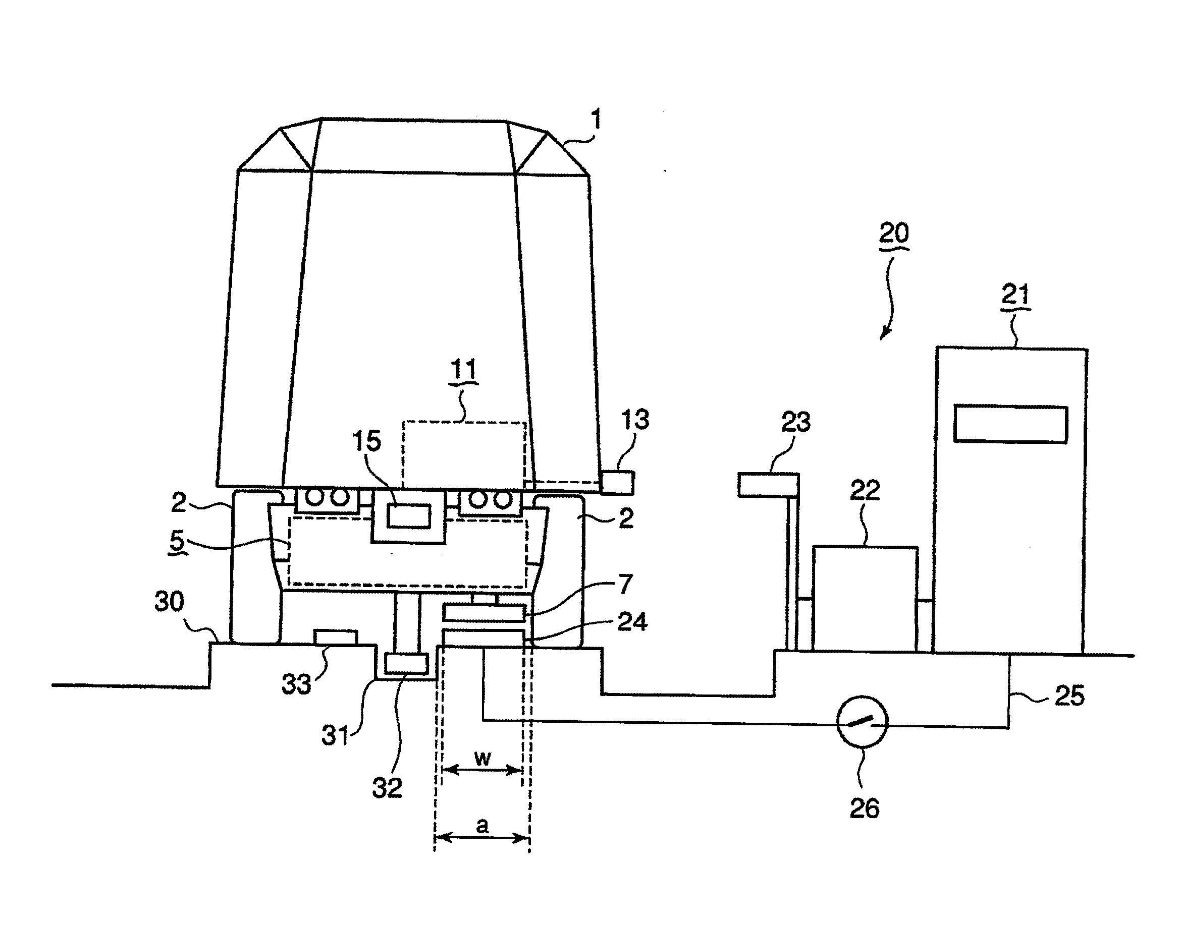
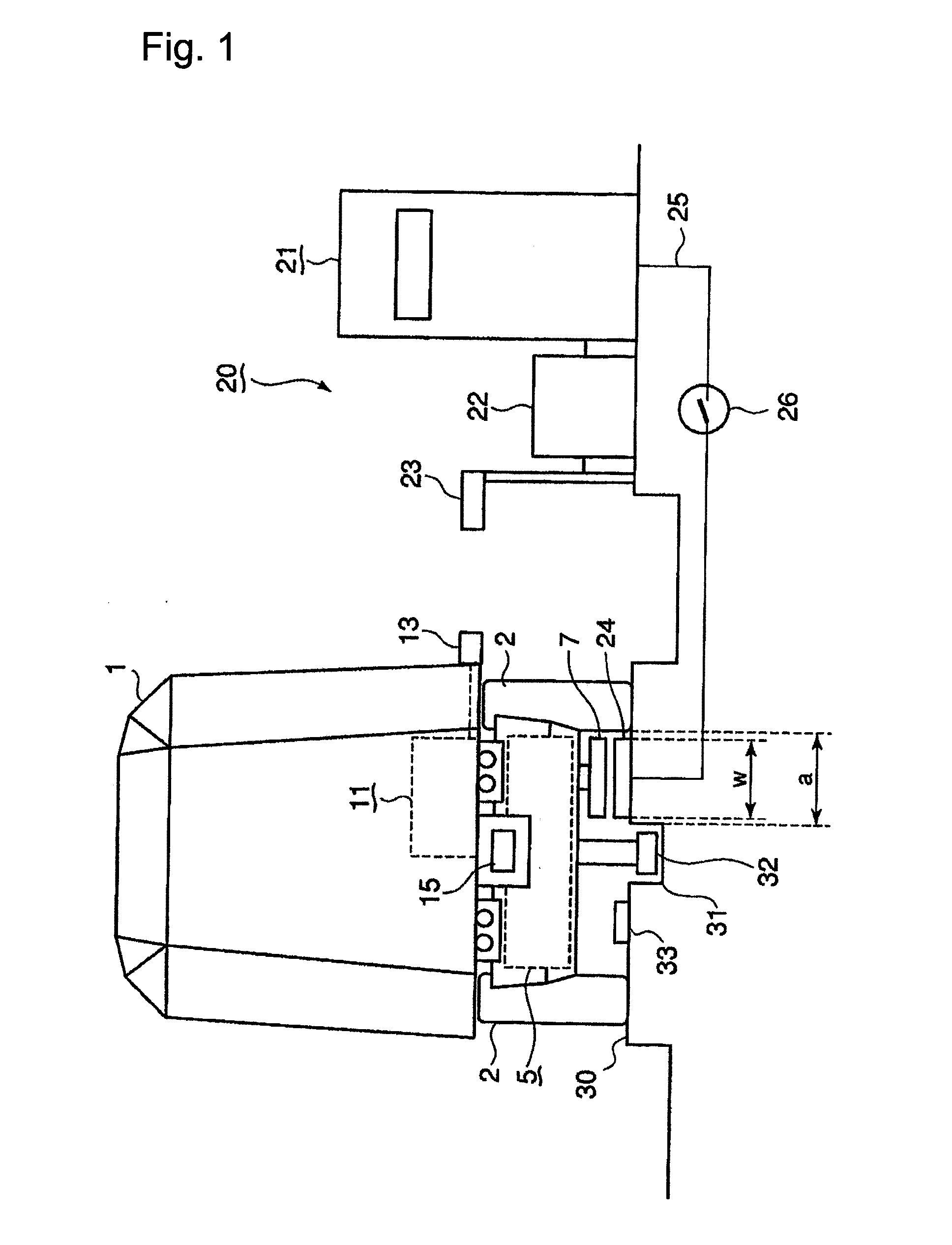
[0061]Referring to FIG. 1, a vehicle 1 in a track type traffic system is an electric vehicle which is equipped with rubber tires 2 as wheels at four corners of the bottom of the vehicle, and adapted to run on a predetermined track (a running road surface 30 in this embodiment) under electric power.

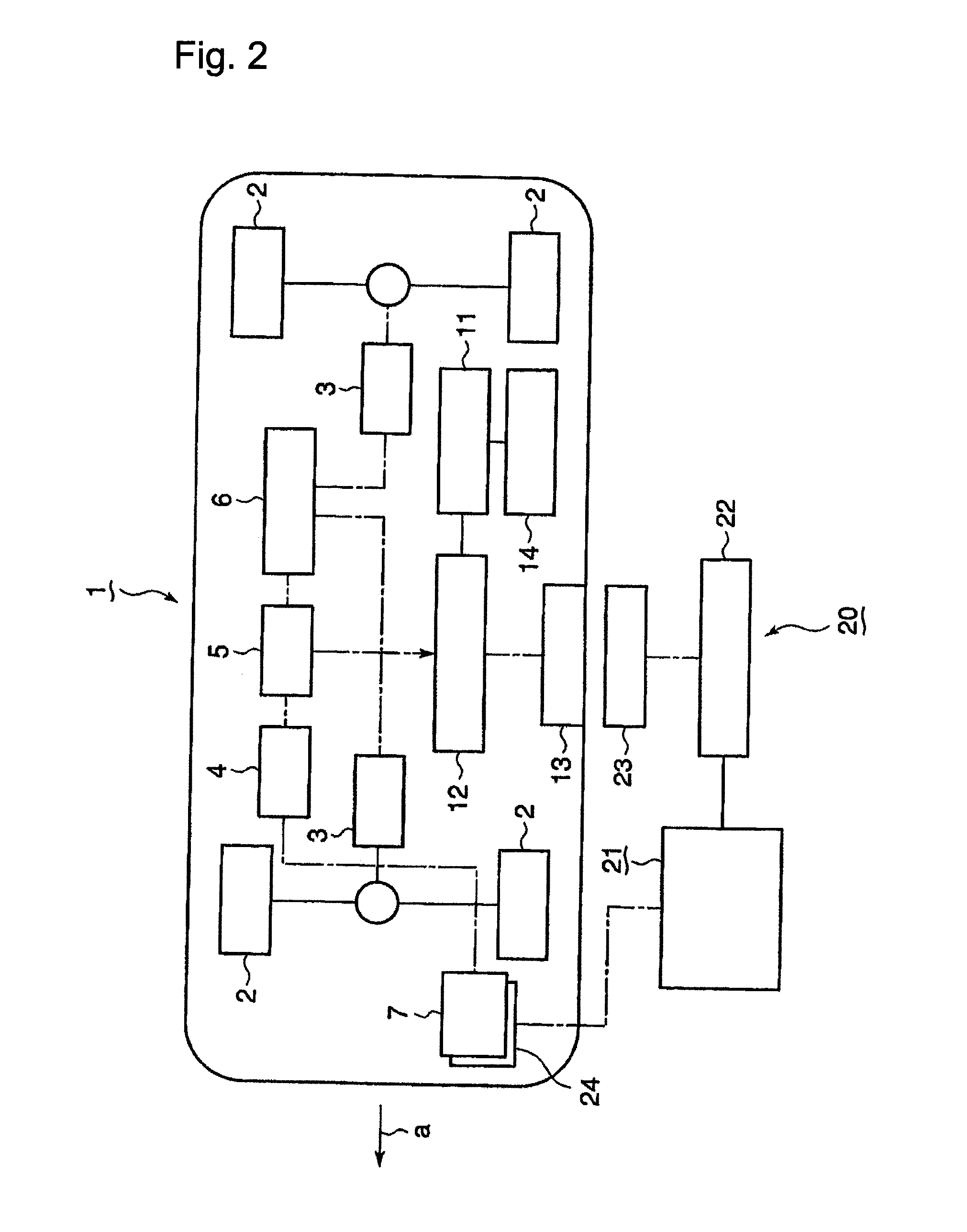
[0062]Referring to FIG. 2, the vehicle 1 incorporates motors 3 for driving the rubber tires 2, a secondary storage cell (for example, a lithium ion secondary storage cell) 5 for feeding drive currents to the motors 3, and a controller 6 for controlling the motors 3. A power receiver 7 is provided in a front lower part of the vehicle 1, and an electric motive force induced in the power receiver 7 is converted by a rectifier 4 into a DC current which is then charged in the secondary storage cell 5.

[0063]Further, the vehicle 1 is mounted therein with a vehicle control unit 11 for controlling th...

embodiment 2

[0101]Next, explanation will be made of a second embodiment of the present invention with reference to FIG. 8 which is a side view illustrating a configuration of a vehicle in a track type traffic system in the second embodiment. Referring to FIG. 8, like reference numerals are used to denote parts having structures like to that of those explained in the first embodiment as stated above. These are also applied all subsequent figures which will be explained hereinbelow. In this embodiment, onboard power receivers 7a, 7b, 7c are arranged in three parts, such as the front, middle and rear parts of the vehicle 1, respectively, and ground power receivers 7a, 7b, 7c are provided on a running road surface 30 at three positions which are opposed face-to-face to the three onboard power receivers 7a, 7b, 7c of the vehicle 1 which has come to a stop. The onboard power receivers 7a, 7b, 7c are flat plate-like as explained in the first embodiment, and they can be easily arranged at places betwee...

embodiment 3

[0103]Next, explanation will be made of a third embodiment of the present invention with reference to FIG. 9 which is an elevation view illustrating a configuration of a vehicle stopped in a station or the like. Referring to FIG. 9, a ground power feeder 24 is provided onto a roof 63 which is supported by a support column 61 standing upright on a platform 61 in the station or the like. A power feed line 25 connected to a charging power source 21 is laid through the insides of the support column 62 and the roof 63, and is connected to the ground power feeder 24 through the intermediary of a ground charge control unit 22.

[0104]Meanwhile, a vehicle power receiver 7 which is provided on the upper surface of the roof of the vehicle is opposed face-to-face to the ground power feeder 24 with a predetermined gap therebetween when the vehicle 1 comes to a stop at the platform 61. In this embodiment, since the onboard power receiver 7 is flat plate-like, as stated above, it is easily mounted ...


PUM


Abstract

Provided is a noncontact type power feeder system for feeding an electric power to a mobile object, which enables a quick charge and transmission of a high electric power and in which a power feeder and a power receiver can be readily manufactured at low cost, comprising a power feeder arranged along a running road surface for the mobile object 1, and a power receiver mounted to the mobile object, the power feeder and the power receiver being opposed fact-to-face to each other for feeding an electric power, wherein the power feeder is secured on the running road surface for the mobile object, or aerially above the running road surface while the power receiver is mounted at a position where the power receiver is opposed face-to-face to the power feeder with a predetermined gap therebetween when the mobile object is stopped at a position where the power feeder is set up, and each of the power feeder and the power receiver is composed of a planer core having long sides extended in the travel direction of the mobile object while the power feeder is fed thereto with an electric power through a power feed line laid underground or aerially.

Description

BACKGROUND OF THE INVENTION[0001]1. Technical Field[0002]The present invention relates to a power feeder system for feeding an electric power in a non-contact manner to a power receiver provided, for example, on a mobile object such as an electric car or an electric vehicle in a track type traffic system from a power feeder provided in a track such as a railway or a road surface on which the mobile object or the like runs.[0003]2. Description of the Related Art[0004]Heretofore, there have been developed a various kinds of non-contact type power feeder systems for feeding an electric power to an electrically driven mobile object in a non-contact manner. The non-contact type power feeding system is adapted to charge an electric power to a power receiver from a power feeder which faces the power receiver with a gap therebetween, in a non-contact type with the use of electromagnetic induction. A vehicle in a new traffic system or the like in which the vehicle runs on a predetermined pat...

Claims


Application Information

Patent Timeline
IPC IPC(8): H01F38/14B60L5/00B60M7/00H02J7/00
CPCB60L5/005H02J5/005B60L2200/26H02J7/0029H02J50/402H02J50/80H02J50/90H02J50/70H02J50/10Y02T10/70Y02T10/7072Y02T90/12B60L53/36B60L53/38B60L2260/22B60Y2200/91B60Y2400/301H02J7/00
Inventor MITAKE, MASAYAMORITA, KATSUAKIYAMAGUCHI, MASAHIROYAMASHITA, HIROSHIYAMADA, MASAOMIKATAHIRA, KOUSUKE
Owner MITSUBISHI HEAVY IND ENG LTD
Why Eureka
Try Eureka