Blower and heat pump apparatus using the same

Active Publication Date: 2011-08-11
MITSUBISHI ELECTRIC CORP
View PDF13 Cites 10 Cited by
  • Summary
  • Abstract
  • Description
  • Claims
  • Application Information

AI Technical Summary

Benefits of technology

[0010]With the blower according to the present invention, the rear edge side outer peripheral edge of the propeller fan that is rotated and driven by the propeller fan drive unit is surrounded by the bell mouth. A plate is provided in at least one direction at the outside of the propeller fan in the radial direction configuring the air duct from the suction side to the blow-out side. At the first position where the distance between the propeller fan and the plate configuring the outside air duct in the radial direction is relatively narrow, the cross-section of the bell mouth at the first position in the vicinity where the blade of the propeller fan approaches the most is configured such that the expansion angle of the bell mo

Problems solved by technology

However, even if taking the air conditioning outdoor unit on which a propeller fan type blower is mounted for an example, it is common that the suction space outside the radial direction of the blade is constituted by a plurality of side faces, the cros

Method used


Image

  • Blower and heat pump apparatus using the same
  • Blower and heat pump apparatus using the same
  • Blower and heat pump apparatus using the same

Examples


embodiment 1

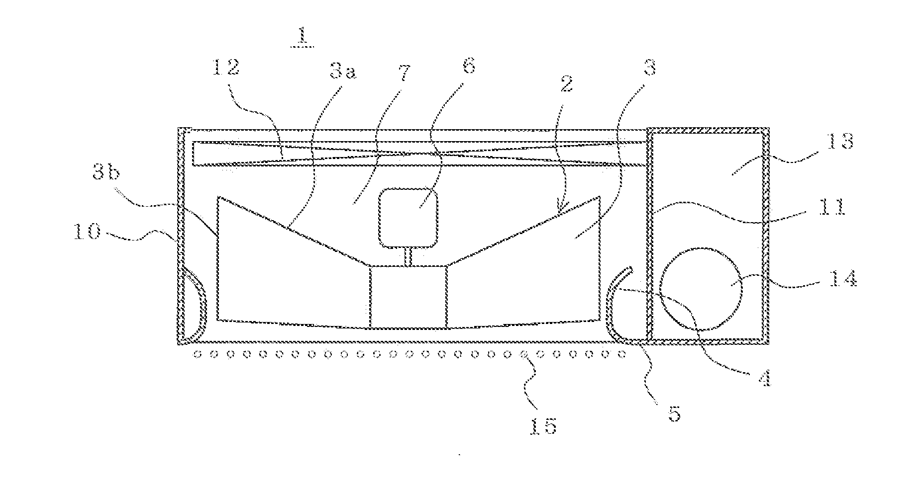
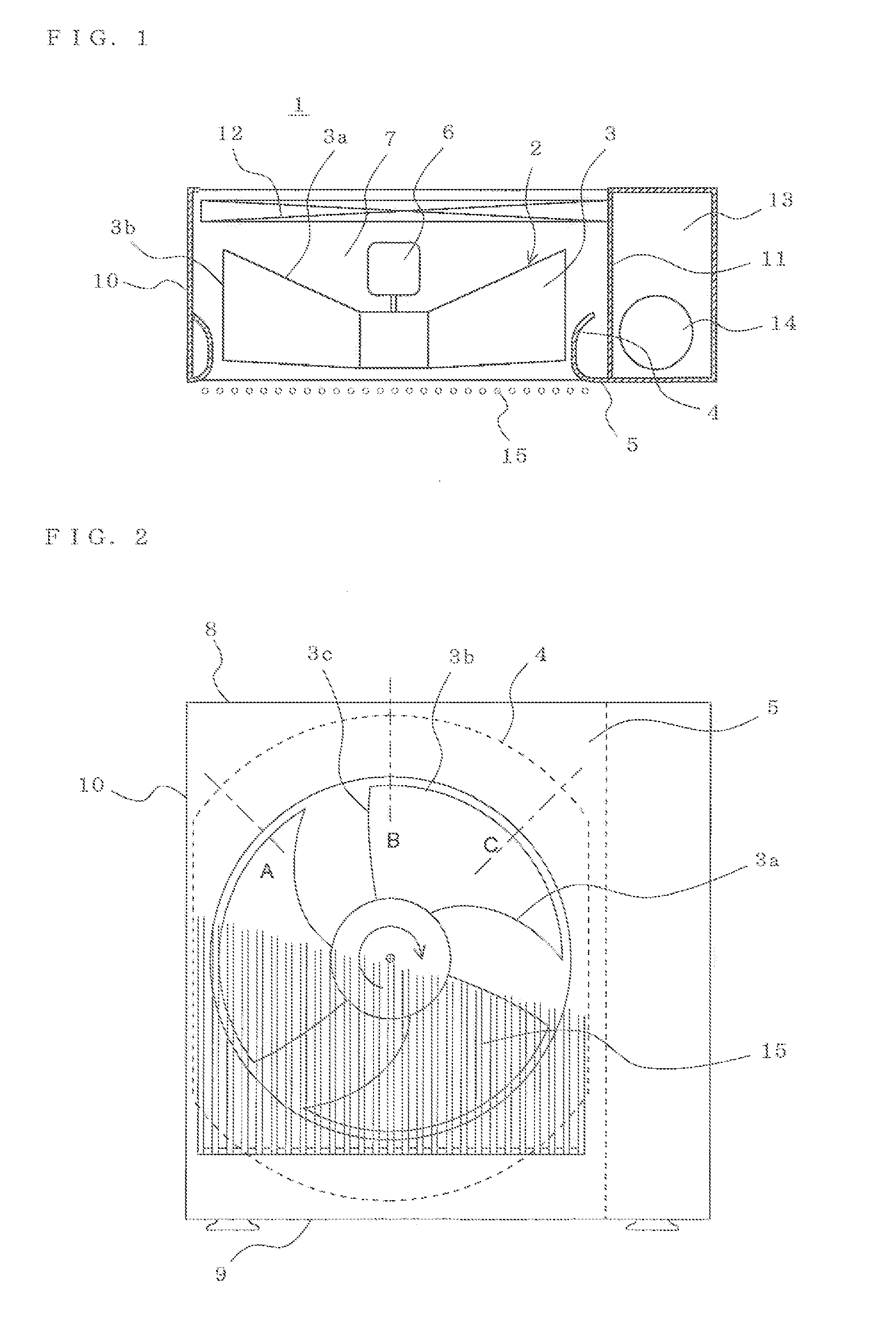
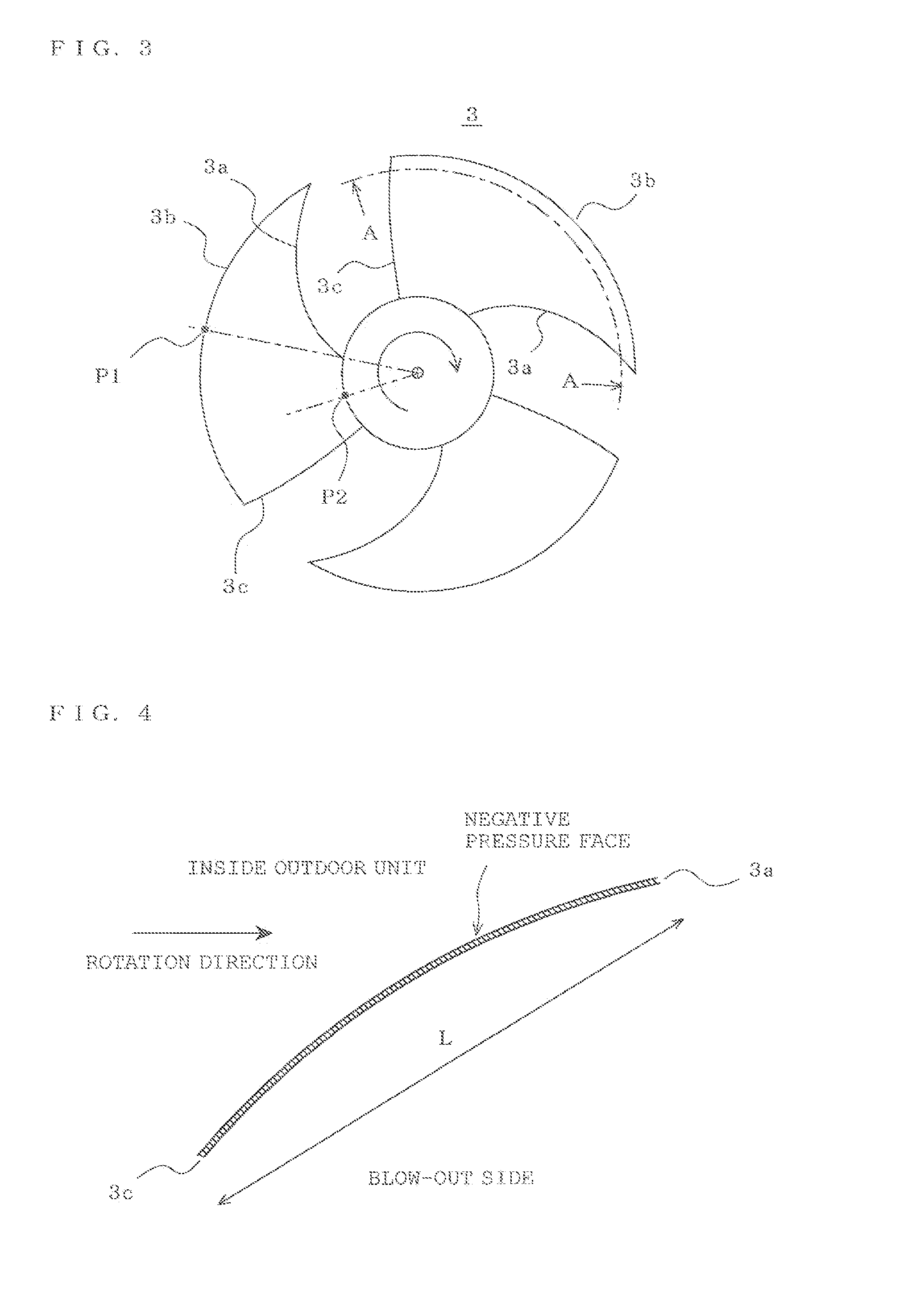
[0025]FIG. 1 is a horizontal sectional view showing an outdoor unit of an air-conditioner of Embodiment 1 of the present invention. FIG. 2 is an elevation view showing the outdoor unit of the air-conditioner of Embodiment 1 of the present invention. FIG. 3 is the elevation view of a propeller fan installed in the outdoor unit of the air-conditioner of Embodiment 1 of the present invention. FIG. 4 is a cylindrical sectional development diagram of the propeller fan installed in the outdoor unit of the air-conditioner of Embodiment 1 of the present invention. FIG. 5 is a sectional view showing shape of a bell mouth at portion A of FIG. 2. FIG. 6 is a sectional view showing shape of a bell mouth at portion B of FIG. 2. FIG. 7 is another elevation view showing the outdoor unit of the air-conditioner of Embodiment 1 of the present invention. FIG. 8 is a supplemental sectional view illustrating features of the bell mouth of the outdoor unit of the air-conditioner of Embodiment 1 of the pre...

embodiment 2

[0074]FIG. 10 is a horizontal sectional view showing the outdoor unit of the air-conditioner of Embodiment 2 of the present invention. FIG. 11 is an elevation view showing the outdoor unit of the air-conditioner. A protection grill is omitted.

[0075]While the opposite side of the machine room 13 is the side plate 10 when viewed from the front face of the propeller fan 3 in Embodiment 1, the opposite side of the machine room 13 is the heat exchanger 12 in Embodiment 2. The face opposing the blow-out plate 5 is covered by the heat exchanger 12 like Embodiment 1.

[0076]In the vicinity of the propeller fan 3, degree of a negative pressure is strong and when there is the heat exchanger 12, which is a resistive element that makes a gas to pass through to outside the radial direction near the propeller fan 3, the speed of the gas flowing into the propeller fan 3 changes according to the distance from the propeller fan 3. Therefore, changes in air flow around the blade of the propeller fan 3 ...

embodiment 3

[0083]FIG. 13 is a horizontal sectional view showing an outdoor unit of a heat pump type water heater of Embodiment 3. FIG. 14 is an elevation view showing the outdoor unit of the heat pump type water heater, the protection grill being omitted. In Embodiment 3, the heat exchanger 12 is located at the opposite side of the machine room 13 like Embodiment 2, the face opposing the blow-out plate 5 is covered by the heat exchanger 12, and a water heat exchanger 17 is installed that performs heat exchange between the refrigerant and water at the lower part in the outdoor unit 1.

[0084]The water heat exchanger 17 occupies the lower part in the outdoor unit 1 and the upper face 17a of the air duct chamber becomes a face of the board constituting the air duct chamber 7.

[0085]That is, the cross-section of the air duct chamber 7 is a horizontally long shape viewed from the front face such that the length of the heat exchanger 12 and machine room plate 11 is shorter than the length of the upper ...


PUM


Abstract

The rear side outer peripheral edge of a propeller fan rotated and driven by a motor, of a propeller fan drive unit, is surrounded by a bell mouth. An upper plate, a lower plate, a side plate, and a machine room plate constitute an air duct at the suction side, outside the radial direction of the propeller fan. The cross-section of the bell mouth, at a first position in the vicinity where a blade of the propeller fan is closest, and where the distance between the propeller fan and the plate constituting the air duct outside the radial direction is relatively narrow, is made to be such that an expansion angle θ1 of the bell mouth suction side is made small. The overlapped height Hb of the propeller fan and the bell mouth is made large against a cross-section at a second position where the distance between the propeller fan and a plate is relatively large. The shape of the cross-section of the bell mouth is made to change gradually between the first position and the second position.

Description

TECHNICAL FIELD[0001]The present invention relates to a blower having a bell mouth and an impeller, and a heat pump apparatus using the blower.BACKGROUND ART[0002]With apparatuses provided with such as a propeller fan type blower and an outdoor unit of an air-conditioner (hereinafter, an air conditioning outdoor unit), to minimize turbulence and variations of inflow air into the blower is indispensable in order to reduce aerodynamic noises.[0003]To achieve reduction of aerodynamic noises, it is effective to reduce a relative speed of a blade and a gas by making the diameter of an impeller large and to reduce an absolute speed of the gas by securing a passing cross sectional area of the gas.[0004]In order to reduce turbulence and variations of inflow air into the blower, it is ideal to suction a gas with a rotation axis being the center from a sufficiently wide space which is homogeneous in the circumferential direction. However, even if taking the air conditioning outdoor unit on wh...

Claims


Application Information

Patent Timeline
IPC IPC(8): F25B13/00F01D25/24F04D29/38F04D29/54F04D29/66F24F1/00
CPCF04D29/162F04D29/164F24F1/40F04D29/663F24F1/38F04D29/526
Inventor KATO, YASUAKITADOKORO, TAKAHIDEBABA, MASANOBUTAKADA, HIROYUKI
Owner MITSUBISHI ELECTRIC CORP
Why Eureka
Try Eureka