Solar power management system

a solar power management and solar energy technology, applied in the field of solar power management system, can solve the problems of low sunlight energy conversion efficiency, largely increased demand of people for more energy sources, and environmental pollution

Inactive Publication Date: 2011-08-11
NAT CHIAO TUNG UNIV
View PDF4 Cites 62 Cited by
  • Summary
  • Abstract
  • Description
  • Claims
  • Application Information

AI Technical Summary

Benefits of technology

(1) The solar power management system can regulate the photovoltaic cell or the photovoltaic cell module to a maximum power and thereby improves the drawback in the prior art that only regulates the solar power management system to output a maximum power. Thus, the photovoltaic cell or the photovoltaic cell module can output the maximum power without exceeding the high limit.

Problems solved by technology

The consumption of traditional energy resources has caused environmental pollution and drastic changes in global climate, which in turn indirectly leads to the largely increased demands of people for more energy sources.
Although solar radiation can be converted into electric energy through solar photovoltaic technology, and light energy from the sun is non-depletable, the currently available sunlight energy conversion efficiency is relatively low.
As a result, the output current and voltage of the solar photovoltaic system is unstable.
The unstable voltage and current generated by the photovoltaic cell module input to the voltage converter at non-optimal settings in most of the time.
Thus, the voltage converter has relatively low power conversion efficiency (PCE).
That is, a large amount of solar energy is wasted.
Accordingly, the voltage converter for this purpose would have complicated structure, large volume, high manufacturing cost, and can not be suitably applied to small-size electronic products, such as mobile phones, portable computers, and personal digital assistants (PDAs).
Moreover, the complicated control circuit of the power management system would consume additional power and could not be suitably applied in the μW-level power management circuit.
While the way suggested in this patent can be easily achieved, it is still difficult to reduce the cost for a supercapacitor with sufficient capacity.
However, since the optimizing strategy is complicated and requires an additional voltage conversion chip, it is very difficult for the power management system based on the SolarMagic™ technology to be configured as a system on chip (SoC).

Method used


Image

  • Solar power management system
  • Solar power management system
  • Solar power management system

Examples


first embodiment

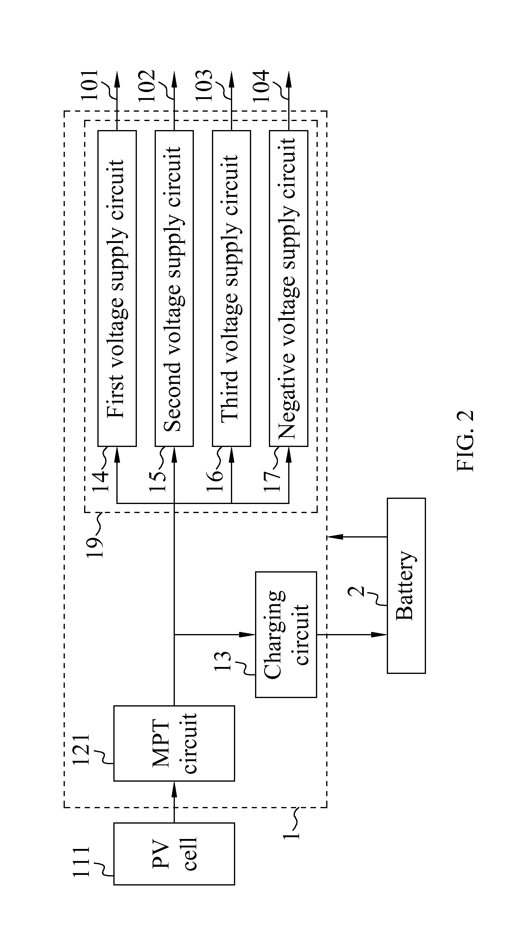
Please refer to FIG. 2 that is a block diagram of a solar power management system 1 according to a first embodiment of the present invention. As shown, the solar power management system 1 is manufactured as a system on chip (SoC) and is connected to an output end of a photovoltaic cell 111 for managing the electric energy conversion by the photovoltaic cell 111, supplying the converted electric energy to an external load, and storing surplus electric energy in a battery 2. The solar power management system 1 comprises a maximum power tracking (MPT) circuit 121, a charging circuit 13, and a voltage conversion module 19. The MPT circuit 121 causes the photovoltaic cell 111 to output electric energy with a maximum power, and the voltage conversion module 19 converts the electric energy with the maximum power into a setting voltage for use by an external load. In the illustrated first embodiment, the voltage conversion module 19 comprises a first voltage supply circuit 14, a second volt...

second embodiment

The solar power management system 1 according to the second embodiment of the present invention is structurally similar to the first embodiment as shown in FIG. 2, and comprises an MPT circuit 121, a charging circuit 13, and a voltage conversion module 19. The voltage conversion module 19 further comprises a first voltage supply circuit 14, a second voltage supply circuit 15, a third voltage supply circuit 16, and a negative voltage supply circuit 17. Please refer to FIG. 5. The third voltage supply circuit 16 comprises a comparison circuit 1601, a finite-state machine 1602, and a switched-capacitor DC-DC converter 1603. The switched-capacitor DC-DC converter 1603 further comprises a first switched capacitor matrix 16031 and a second switched capacitor matrix 16032. The comparison circuit 1601 compares a reference voltage Vref with a feedback voltage Vout for the finite-state machine 1602 to output a control signal according to a comparison result from the comparison circuit 1601, s...

third embodiment

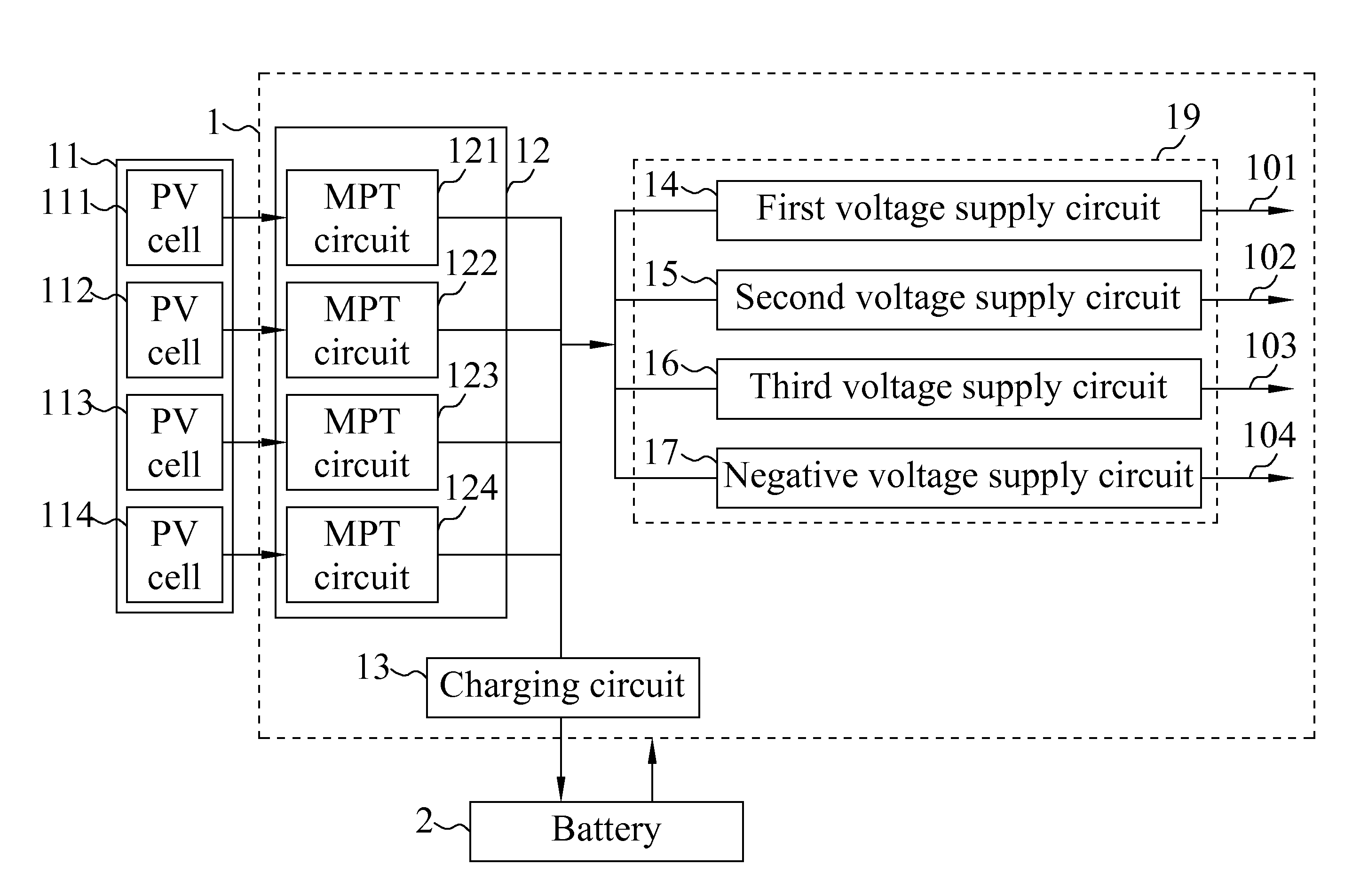
Please refer to FIG. 3 that is a block diagram of a solar power management system 1 according to a third embodiment of the present invention for use with a photovoltaic cell module 11. In the illustrated third embodiment, the photovoltaic cell module 11 comprises four photovoltaic cells 111, 112, 113, 114, which are connected in parallel to form an array. However, it is understood the number and the connecting manner (in parallel or in series) of the photovoltaic cells included in the photovoltaic cell module 11 are not necessarily restricted to the above mentioned number and connecting manner. The solar power management system 1 in the third embodiment comprises four MPT circuits 121, 122, 123, 124; a charging circuit 13; and a voltage conversion module 19. The four MPT circuits 121, 122, 123, 124 together constitute a multiphase maximum power tracking (MPT) module 12, and respectively correspond to the four photovoltaic cells 111, 112, 113, 114. Further, the four MPT circuits 121,...


PUM

PropertyMeasurementUnit
voltageaaaaaaaaaa
voltageaaaaaaaaaa
voltageaaaaaaaaaa

Abstract

A solar power management system is provided for managing electric energy conversion by a photovoltaic cell module, supplying the converted electric energy to an external load, and storing the converted electric energy in a battery. The solar power management system comprises a multiphase maximum power tracking (MPT) module, a charging circuit, and a voltage conversion module. The multiphase MPT module regulates output current of the photovoltaic cell module to output maximum power within the high limit thereof and obtain improved solar energy conversion efficiency. The voltage conversion module converts the electric energy generated by the photovoltaic cell module into different voltage formats, such as 5.6V DC, 1.0V DC, 0.6˜0.3V DC low voltage, or −1.2V DC negative voltage, to meet different external load requirements. The solar power management system has simple circuitry and can be configured as a system on chip (SoC) at reduced cost while provides very wide applications.

Description

FIELD OF THE INVENTIONThe present invention relates to a solar power management system, and more particularly to a power management system capable of tracking changes in the solar power conversion efficiency of a photovoltaic cell.BACKGROUND OF THE INVENTIONThe consumption of traditional energy resources has caused environmental pollution and drastic changes in global climate, which in turn indirectly leads to the largely increased demands of people for more energy sources. To solve the problem of worldwide energy shortage, all the countries in the world are devoted to the exploitation of alternate energy resources and expect the alternate energy resources can reduce people's demands for the traditional energy resources to thereby solve the worldwide energy crisis. Although solar radiation can be converted into electric energy through solar photovoltaic technology, and light energy from the sun is non-depletable, the currently available sunlight energy conversion efficiency is relat...

Claims


Application Information

Patent Timeline
Patent Type & Authority Applications(United States)
IPC IPC(8): H02J7/00
CPCH02J7/35Y02E10/58Y02E10/566H02M3/07Y02E10/56
Inventor WU, CHUN-YIHSIEH, WEI-CHIHHWANG, WEI
Owner NAT CHIAO TUNG UNIV
Why Eureka
Try Eureka