Charge Storage Device

a technology of energy storage and charge, which is applied in the direction of hybrid capacitor electrolytes, capacitors, electrical equipment, etc., can solve the problems of large uncertainty in the use of rc time constant as a measure of capacitor suitability, low energy delivered, etc., and achieves a wide range of operating temperature and high thermal shock.

Active Publication Date: 2011-08-11
CAP XX LTD
View PDF7 Cites 12 Cited by
  • Summary
  • Abstract
  • Description
  • Claims
  • Application Information

AI Technical Summary

Benefits of technology

[0046]It is an object of the invention in its preferred form to provide a supercapacitor that is substantially capable of withstanding high thermal shock and affording a broad range of operating temperature.

Problems solved by technology

Supercapacitors generally enable fast (high power) delivery of energy with the amount of energy delivered being very high compared to ordinary capacitors, but low compared to batteries.
Clearly, the use of RC time constant as a measure of capacitor suitability is subject to a large uncertainty.
It should also be noted that the performance of the devices can not be adequately explained by the hitherto utilised simple RC model.
However, water is susceptible to electrolysis to hydrogen and oxygen and as such has a relatively small electrochemical window of operation outside of which the applied voltage will degrade the solvent.
However, in addition to the specific electrolyte requirements of supercapacitors mentioned above, there is also the practical consideration that supercapacitors do not operate in isolation.
Supercapacitors in soft packages are suitable for use in small numbers of high-end hand held devices and the like, however, soft packages are not so suitable for use in demanding environments, such as motor vehicles or where highly automated assembly is used.
The use of rigid packages, which can be surface mounted is desirable, however, surface mount technology (SMT) has its own drawbacks, including instances of thermal shock during manufacture.
The soldering of a supercapacitor to a circuit board in a surface mount process, such as reflow, creates high temperatures over a relatively short time period.
Due to its generally small mass, a supercapacitor is therefore susceptible to large thermal shock, as only a small amount of heat is required to raise its temperature rapidly.
Where large thermal shock is experienced, expansion, separation or vaporisation of the electrolyte may occur, which may cause performance impairment and may ultimately lead to the supercapacitor's destruction.

Method used


Image

  • Charge Storage Device
  • Charge Storage Device
  • Charge Storage Device

Examples


example 1

Forming a Supercapacitor

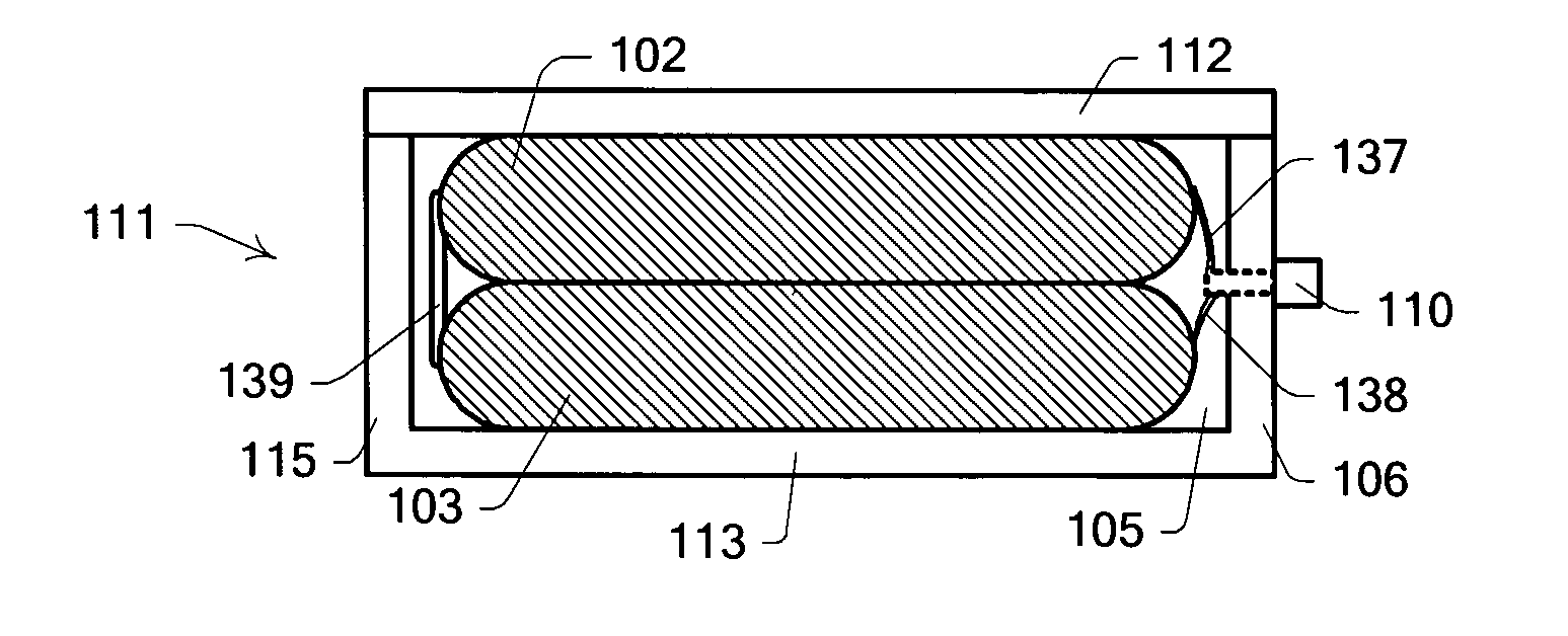
[0150]Electrode sheets formed from 6 μm thick carbon coatings on 22 μm thick aluminium foil were cut to give 29 cm2 of active area and one separator selected from: a 25 μm thick paper separator; a 35 μm thick nylon separator or; a 37 μm thick polypropylene separator was placed between the electrodes. The whole was then folded in half to form a flat electrode stack with bare aluminium tabs extending. The whole was saturated with either: 1M TEATFB / PC; EMITFB; EMITFSI; Py1,3TFSI; EMITFMS or; EMIDCA electrolyte and sealed into a package formed from a polypropylene and aluminium laminate with an EAA sealant layer. The supercapacitor thus assembled had external dimensions of about 60×55×0.4 mm. This general construction is used a standard for materials comparison. Electrical testing results are given in Table 4 and the effect of temperature is given in Table 5 for a like series of samples.

TABLE 4Electrical properties of cells with ionic liquidsCapacitance atESR at ...

example 2

Forming a Supercapacitor and SMT Testing

[0151]Electrode sheets formed from 6 μm thick carbon coatings on 22 μm thick aluminium foil were layered with a 25 μm thick paper separator to form a flat electrode stack of maximum dimensions about 30×15×1 mm. Aluminium tabs (5 mm wide by 100 μm thick) with pre-coated polypropylene sealant layers were attached to opposing ends of the electrode stack. The whole was saturated with EMITFB electrolyte and sealed within a polypropylene and aluminium laminate package designed for packaging lithium-ion batteries. The supercapacitor thus assembled has external dimensions of about 39×17×1.3 mm and the terminals extend about 1.5 cm. The supercapacitor was then approximately evenly coated with a layer of silicone sealant to give an approximately 50×28×15 mm device with the aluminium tabs extending about 5 mm beyond the silicone. After curing overnight, the supercapacitor was heated from room temperature to about 50° C. over about 8 minutes and then to 2...

example 3

Forming a Supercapacitor and SMT Testing

[0152]Electrode sheets formed from 6 μm thick carbon coatings on 22 μm thick aluminium foil were layered with a 25 μm thick paper separator to form a flat electrode stack of maximum dimensions about 30×15×1 mm. Aluminium tabs (3 mm wide by 100 μm thick and about 10 cm long) with pre-coated polypropylene sealant layers were attached to opposing ends of the electrode stack. The whole was saturated with EMITFSI electrolyte and sealed within a polypropylene and aluminium laminate package designed for packaging lithium-ion batteries. The supercapacitor thus assembled has external dimensions of about 39×17×1.3 mm and the terminals extend approximately 10 cm. This supercapacitor cell was then placed within a housing machined from a 49×22×4 mm block of Teflon with a 45×18×2 mm cavity. The terminals were folded to maximise the thermal pathway through them, extending about 7 mm from the housing. The remaining space within the cavity was then filled with...


PUM


Abstract

A supercapacitor capable of withstanding SMT manufacturing conditions comprising at least one pair of electrodes having a mixture of carbon particles preferably in a CMC binder on facing surfaces of the at least one pair of electrodes; a porous separator, preferably polyimide, positioned between the facing surfaces of the at least one pair of electrodes; and an electrolyte for wetting the separator wherein the electrolyte comprises an ionic liquid, such as EMITSFI, and optionally a solvent such as PC, GBL or glutaronitrile.

Description

FIELD OF THE INVENTION[0001]The present invention relates to energy storage devices. In particular, the invention relates to energy storage devices capable of withstanding thermal shock.[0002]The invention has been developed primarily as a supercapacitor capable of withstanding thermal shock, such as encountered in electronics manufacturing using reflow processes and will be described hereinafter with reference to this application. It will be appreciated, however, that the invention is not limited to that particular field of use.[0003]The disclosure of the present application also incorporates by reference the applicant's co-pending applications entitled “A Package For An Electrical Device”, filed on the same date as the present application, (Attorney reference 55817WOP00 and 55818WOP00).BACKGROUND OF THE INVENTION[0004]Any discussion of the prior art throughout the specification should in no way be considered as an admission that such prior art is widely known or forms part of the ...

Claims


Application Information

Patent Timeline
Patent Type & Authority Applications(United States)
IPC IPC(8): H01G9/155
CPCH01G9/038H01G9/155Y02E60/13H01G11/58H01G11/62H01G11/24H01G11/54
Inventor AITCHISON, PHILLIP BRETTBILYK, ALEXANDERNGUYEN, JOHN CHI HUNGKING, WARREN
Owner CAP XX LTD
Why Eureka
Try Eureka