Light Emitting Diode With Metal Piles and Multi-Passivation Layers and Its Manufacturing Method

a technology of light-emitting diodes and metal piles, which is applied in the manufacturing of semiconductor/solid-state devices, semiconductor devices, electrical devices, etc., can solve the problems of reducing the efficiency of reflector layers, and affecting the efficiency of semiconductor light-emitting diodes. , to achieve the effect of reducing the number of pads, preventing light absorption of pads, and enhancing optical power

a technology of light-emitting diodes and metal piles, which is applied in the manufacturing of semiconductor/solid-state devices, semiconductor devices, electrical devices, etc., can solve the problems of reducing the efficiency of reflector layers, and affecting the efficiency of semiconductor light-emitting diodes. , to achieve the effect of reducing the number of pads, preventing light absorption of pads, and enhancing optical power

US20110198635A1Active Publication Date: 2011-08-18KOREA PHOTONICS TECH INST

Image

  • Light Emitting Diode With Metal Piles and Multi-Passivation Layers and Its Manufacturing Method
  • Light Emitting Diode With Metal Piles and Multi-Passivation Layers and Its Manufacturing Method
  • Light Emitting Diode With Metal Piles and Multi-Passivation Layers and Its Manufacturing Method

Examples


Embodiment Construction

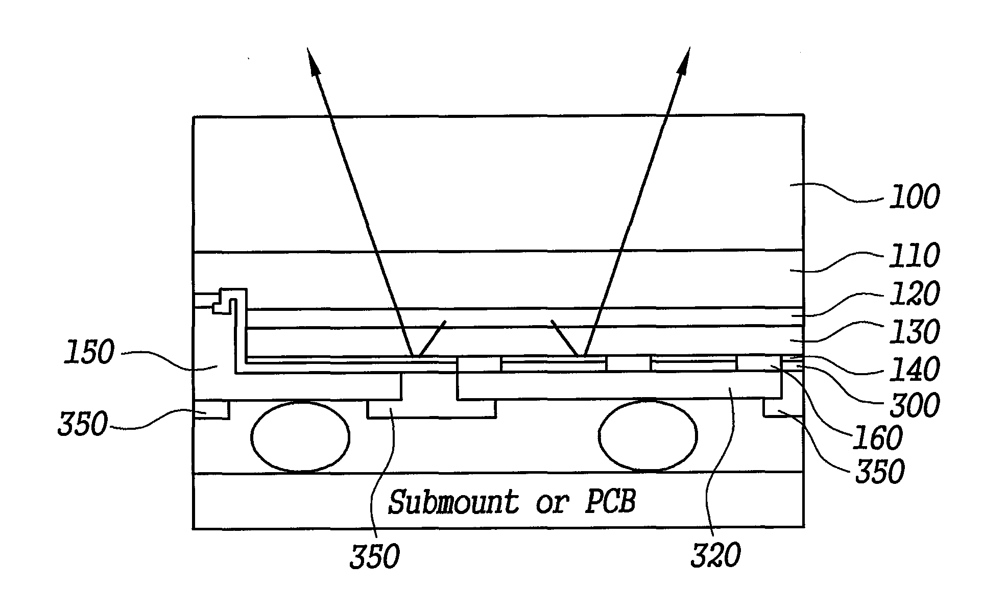
[0120]FIG. 9 is a cross-sectional view of a light emitting diode with pad rearrangement according to an embodiment of the present invention.

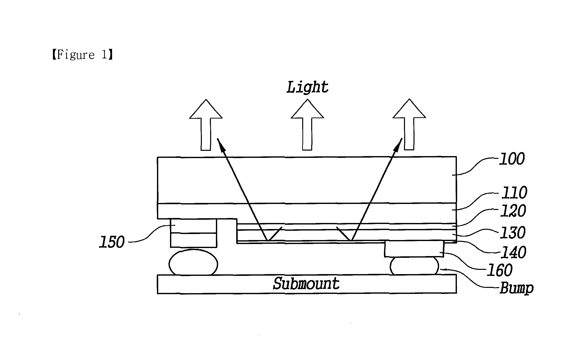
[0121]FIG. 9 shows a substrate 100, a first semiconductor layer 110, an active layer 120, a second semiconductor layer 130, a reflector layer 140, a first electrode 150, a second electrode 160, a first passivation layer 300, a first electrode line 310, a second electrode line 320, a first bonding pad 330, and a second bonding pad 340 (see FIG. 19).

[0122]The first semiconductor layer 110 and the second semiconductor layer 130 are made of GaN, and the layers are stacked on the substrate 100.

[0123]The active layer 120 is formed between the first semiconductor layer 110 and the second semiconductor layer 130.

[0124]The reflector layer 140 is formed on a part of stacked semiconductor layers which are formed of a first semiconductor layer 110, an active layer 120, and a second semiconductor layer 130 in sequence, except the lowered face prepared with m...


PUM


Abstract

The present invention relates to a light emitting diode with metal piles and one or more passivation layers and a method for making the diode including a first steps of performing mesa etching respectively on a first semiconductor layer and a second semiconductor layer belonging to stacked layers formed on a substrate in sequence! a second step of forming a reflector layer on the mesa-etched upper and side face! a third step of contacting one or more first electrodes with the first semiconductor layer and one or more second electrodes through the reflector layer with the second semiconductor layer; a fourth step of forming a first passivation layer on the reflector layer and the contacted electrodes; and a fifth step of connecting the first electrodes to a first bonding pad through one or more first electrode lines, bring one ends of vertical extensions having the shape of a metal pile into contact with one or more second electrodes, and connecting the other ends of the vertical extensions to a second bonding pad through one or more second electrode lines. As effects of the present invention, the loss of light emitting area decreases and current diffusion efficiency increases.

Description

TECHNICAL FIELD[0001]The present invention relates to a light emitting diode and its manufacturing method to enhance luminous efficiency by rearrangement of metal pads adopting metal piles and multi-passivation layers.[0002]In addition, the present invention of pad rearrangement relates to chip scale package of light emitting diode and its manufacturing method. In detail, the present invention may be embodied as a light emitting diode with n type and p type semiconductor layers on a substrate and its manufacturing method, particularly including a primary electrode provided on a semiconductor layer, and a secondary electrode, which is electrically connected to the primary electrode, with a first passivation interposed between the electrodes.BACKGROUND ART[0003]Conventional flip chip semiconductor light emitting diodes are generally used because of high current diffusion efficiency and optical extraction efficiency, and excellent thermal characteristics with a silicon sub mount (see F...

Claims


Application Information

Patent Timeline
18 Aug 2011
Publication
US20110198635A1
IPC
H01L33/60; H01L33/38; H01L33/46
CPC
H01L33/385; H01L33/46; H01L2224/49107; H01L2224/13; H01L2933/0016; H01L2224/05573; H01L2224/05568; H01L2924/00014
Inventors
KIM, SANG MOOK; BAEK, JONG HYEOB