Catalytic layer structure for fuel cell

a fuel cell and catalytic layer technology, applied in the direction of fuel cells, active material electrodes, cell components, etc., can solve the problems of sharp voltage drop, insufficient oxygen, and insufficient oxygen, and achieve high current density, short diffusion distance, and easy preparation

Inactive Publication Date: 2011-08-18
TOYOTA JIDOSHA KK
View PDF6 Cites 10 Cited by
  • Summary
  • Abstract
  • Description
  • Claims
  • Application Information

AI Technical Summary

Benefits of technology

[0018]The catalyst layer for a fuel cell according to the present invention has electroconductive carriers of which the average secondary particle size is controlled to 100 to 180 μm that is smaller than a conventional particle size, when having catalyst particles of which the particle quantity is controlled to 0.05 mg / cm2 to 0.15 mg / cm2 that is smaller than a conventional particle quantity, thereby can reduce the amount of oxygen which is going to adsorb to the surface of, dissolve in and diffuse through the ionomer, per one piece of the secondary particles, and can inhibit oxygen from concentrating on the surface of the ionomer.
[0019]In addition, the catalyst layer for a fuel cell has an ionomer of which the film thickness is controlled to a range from 6 nm to 16 nm that is thinner than a conventional film thickness, and thereby can shorten the diffusion distance of oxygen which has deposited on the ionomer, in the ionomer, while securing the proton conductivity of the ionomer. Accordingly, the catalyst layer for a fuel cell can alleviate a rate-controlled condition by the concentration diffusion process of oxygen in the catalyst, and can make the oxygen more quickly arrive at catalyst particles which are dispersed on and carried by the electroconductive carrier. Accordingly, the catalyst layer for a fuel cell can prevent the sudden drop of voltage due to the lack of oxygen, in a high current density region, and can make the fuel cell output a desired power.
[0020]In the catalyst layer for a fuel cell according to the present invention, an average primary particle size of the electroconductive carrier is preferably in a range of 5 nm to 15 nm (claim 2). The electroconductive carrier in the catalyst layer for a fuel cell according to the present invention has the average secondary particle size controlled to a range of 45 nm to 135 nm which is smaller than the conventional particle size, and can be easily prepared by controlling the average primary particle size of the electroconductive carrier to a range from 5 nm to 15 nm.
[0021]In the catalyst layer for a fuel cell according to the present invention, the catalyst is carried preferably at a density in a range of 15 wt % to 35 wt %. The catalyst layer for a fuel cell according to the present invention has the catalyst carried at the density controlled in a range of 15 wt % to 35 wt % which is lower than a conventional density, when having the catalyst particles of which the particle quantity is approximately equal to the conventional particle quantity, thereby makes the thickness of the catalyst layer thicker and can more disperse the catalyst particles therein. Accordingly, the catalyst layer for a fuel cell can reduce the amount of oxygen which is going to adsorb to the surface of, dissolve in and diffuse through the ionomer, per one piece of the secondary particles, and can inhibit oxygen from concentrating on the surface of the ionomer.
[0022]The catalyst layer for a fuel cell according to the present invention can reduce the amount of oxygen which is going to adsorb to the surface of, dissolve in and diffuse through the ionomer, per one piece of the secondary particles, and can inhibit oxygen from concentrating on the surface of the ionomer. In addition, the catalyst layer for a fuel cell can shorten the diffusion distance of the oxygen which has deposited on the ionomer, in the ionomer, while securing the proton conductivity of the ionomer.
[0023]Accordingly, the catalyst layer for a fuel cell can alleviate a rate-controlled condition by the concentration diffusion process of oxygen in the catalyst, and can make the oxygen more quickly arrive at catalyst particles which are dispersed on and carried by the electroconductive carrier. Accordingly, the catalyst layer for a fuel cell can prevent the sudden drop of voltage due to the lack of oxygen, in a high current density region, and the fuel cell can output a desired power.

Problems solved by technology

However, if the content of the catalyst particles is set in the range of 0.05 mg / cm2 to 0.15 mg / cm2 which is greatly less than that in the conventional one in order to reduce the amount of platinum to be used, oxygen concentrates on the surface of the ionomer which covers a catalyst, oxygen becomes insufficient in the high current density region due to the rate-controlled condition by the concentration diffusion process of oxygen, and the drop phenomenon in which voltage sharply decreases has occurred.
For instance, a conventional technology of improving the activity by using an alloyed Pt—Cu and the like is effective in raising a voltage value in a low current density region, but when the content of the catalyst particles is as low as in the above description, oxygen becomes insufficient in the high current density region, and the fuel cell has not been capable of outputting a desired power.
In addition, when the conventional core shell is used, the amount of platinum to be used can be reduced, but gold is used for the core, and accordingly the cost has not been able to be lowered.

Method used


Image

  • Catalytic layer structure for fuel cell
  • Catalytic layer structure for fuel cell
  • Catalytic layer structure for fuel cell

Examples


examples

[0065]Next, examples of the present invention will be described below. In the present examples, (1) particle size, (2) particle quantity of catalyst particles, (3) coating thickness of ionomer and (4) carried density of catalyst were respectively measured in the following respective methods.

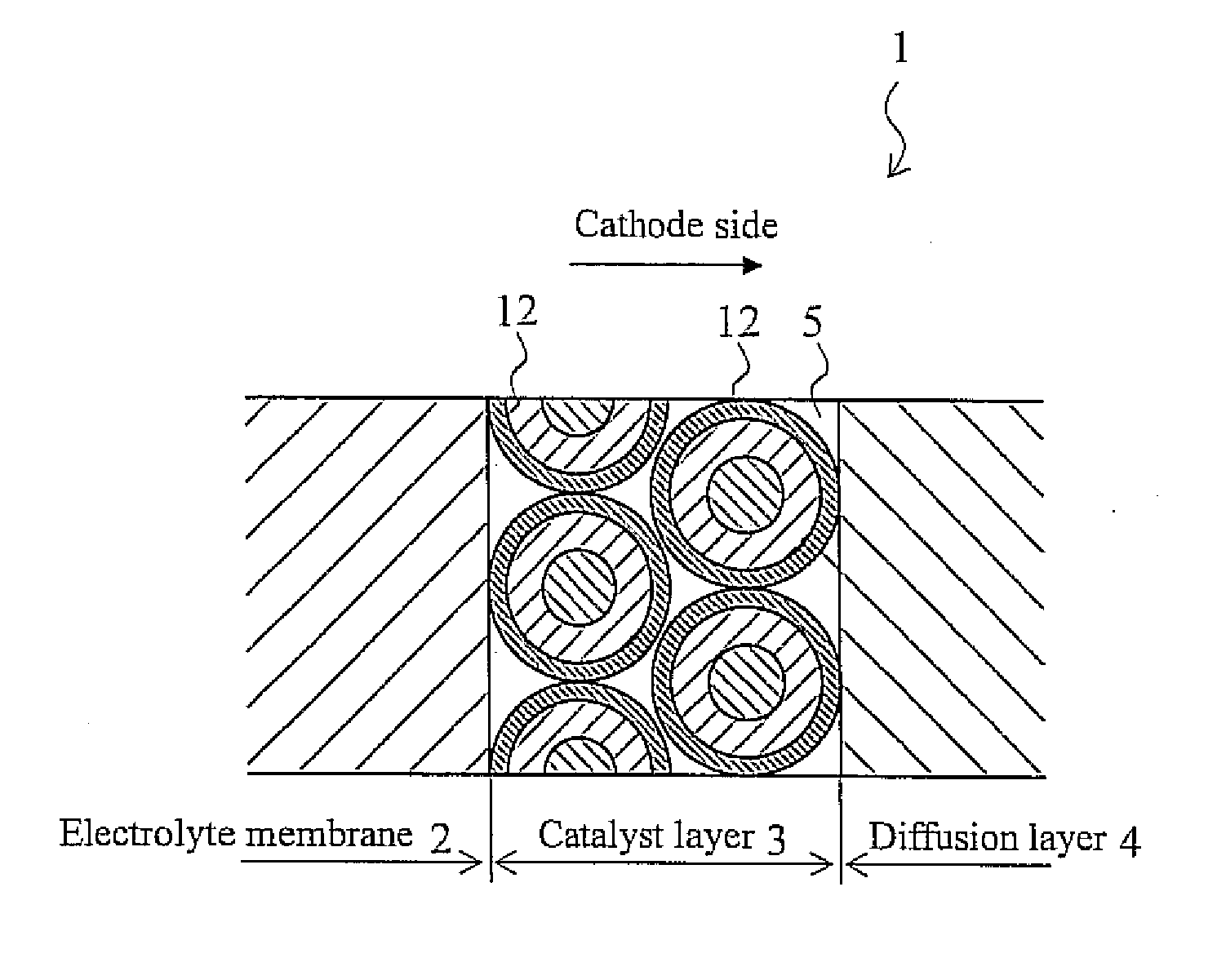
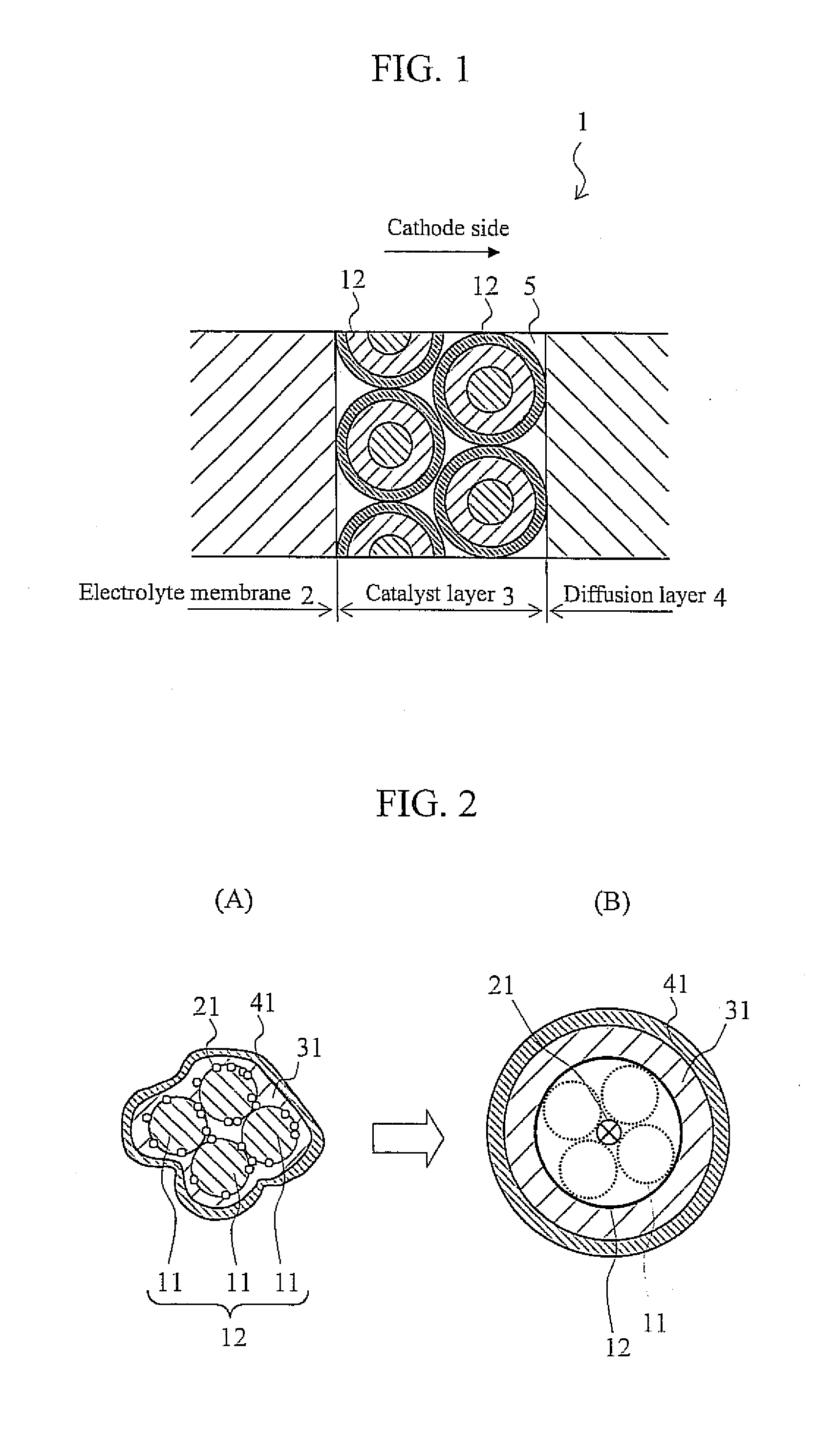
[0066](1) Measurement of Particle Size[0067]The secondary particle size is measured by directly observing the state (carbon particle+Pt+ionomer) of the catalyst layer that has been prepared by making a carbon particle which is an electroconductive carrier carry platinum (Pt) thereon which is a catalyst particle and by wrapping the periphery with the ionomer, or by indirect calculation.

[0068]There are directly observing methods of (a) confirming the state with a three-dimensional TEM (transmission electron microscope), (b) cutting the cross section and observing the cut surface, and (c) observing the surface which has been dyed by a chemical, with an SEM (scanning electron microscope). The indirec...


PUM

PropertyMeasurementUnit
secondary particle sizeaaaaaaaaaa
thicknessaaaaaaaaaa
sizeaaaaaaaaaa

Abstract

An object according to the present invention is to provide a catalyst layer for a fuel cell, which prevents the lowering of the performance due to the lack of oxygen in a high current density region and can provide a desired power, even when containing a small amount of catalyst particles. The catalyst layer for a fuel cell has a structure including: an electroconductive carrier made of a secondary particle which is formed by agglomerating a plurality of primary particles; catalyst particles which are dispersed on and carried by the electroconductive carrier; and an ionomer which covers the electroconductive carrier and the catalyst particles, wherein the catalyst particles have the particle quantity in a range of 0.05 mg/cm2 to 0.15 mg/cm2, the electroconductive carriers have the average secondary particle size in a range of 100 nm to 180 nm, and the ionomer has the film thickness in a range of 6 nm to 16 nm. Thereby, the catalyst layer for a fuel cell can reduce the amount of oxygen per one piece of the secondary particles to inhibit oxygen from concentrating on the surface of the ionomer, and shortens the diffusion distance of oxygen in the ionomer to alleviate a rate-controlled condition by the concentration diffusion process of oxygen in the catalyst layer.

Description

BACKGROUND OF THE INVENTION[0001]1. Field of the Invention[0002]The present invention relates to a catalytic layer structure for a fuel cell and particularly relates to a catalytic layer structure in a cathode side of the fuel cell.[0003]2. Background Art[0004]A polymer electrolyte fuel cell (PEFC) is known as one form of a fuel cell. The polymer electrolyte fuel cell works at a lower temperature (approximately 80° C. to 100° C.), can be manufactured at a lower cost, and can be more compactly formed than fuel cells of other forms, and accordingly is expected to serve as a power source of an automobile or the like.[0005]The polymer electrolyte fuel cell has a catalyst layer and a gas diffusion layer of an anode side stacked on one side of a solid polymer electrolyte membrane which is an ion exchange membrane and has a catalyst layer and a gas diffusion layer of a cathode side stacked on the other side, and makes the layers sandwiched between a separator provided with a fuel gas chann...

Claims


Application Information

Patent Timeline
Patent Type & Authority Applications(United States)
IPC IPC(8): H01M4/86
CPCH01M4/8892H01M4/9075Y02E60/50H01M2008/1095H01M4/926
Inventor MORINAGA, MASAHIKO
Owner TOYOTA JIDOSHA KK
Why Eureka
Try Eureka