Synchronous Induced Wind Power Generation System

a technology of synchronous induced wind power and wind power generation, which is applied in the direction of electric generator control, liquid fuel engine, machines/engines, etc., can solve the problems of inability to achieve large-scale adoption of wind power as an alternative means, difficulty in repair and maintenance of large-scale systems, and limited effect of conventional wind power generation systems

Inactive Publication Date: 2011-08-25
SKALA JAMES A
View PDF10 Cites 20 Cited by
  • Summary
  • Abstract
  • Description
  • Claims
  • Application Information

AI Technical Summary

Benefits of technology

[0026]The permanent magnets are preferably capable of providing braking power equivalent to the maximum rated wind speed of the system, such that with the permanent magnets in place, the system will not be damaged by winds up to the maximum wind rating with the generator off line and unattended.
[0027]In a preferred embodiment, the synchronous induced wind power generation of the first embodiment above is provided, wherein the interior area of the turbine-generator section between the air inlet shroud and the air discharge shroud i

Problems solved by technology

However, the effectiveness of conventional wind power generation systems have been limited by various difficulties such as, for example, the inconsistency of the wind, appropriate locations for placement of wind power generation system far from load centers and the problems of long distance transmission of power, difficulty in repair and maintenance of large systems, etc.
These difficulties have inhibited large scale adoption of wind power as an alternate means of energy.
However, the longer blades require a supporting tower having a corresponding increased height and size.
Further, such large size blades prevent placement of conventional wind

Method used


Image

  • Synchronous Induced Wind Power Generation System
  • Synchronous Induced Wind Power Generation System
  • Synchronous Induced Wind Power Generation System

Examples


Embodiment Construction

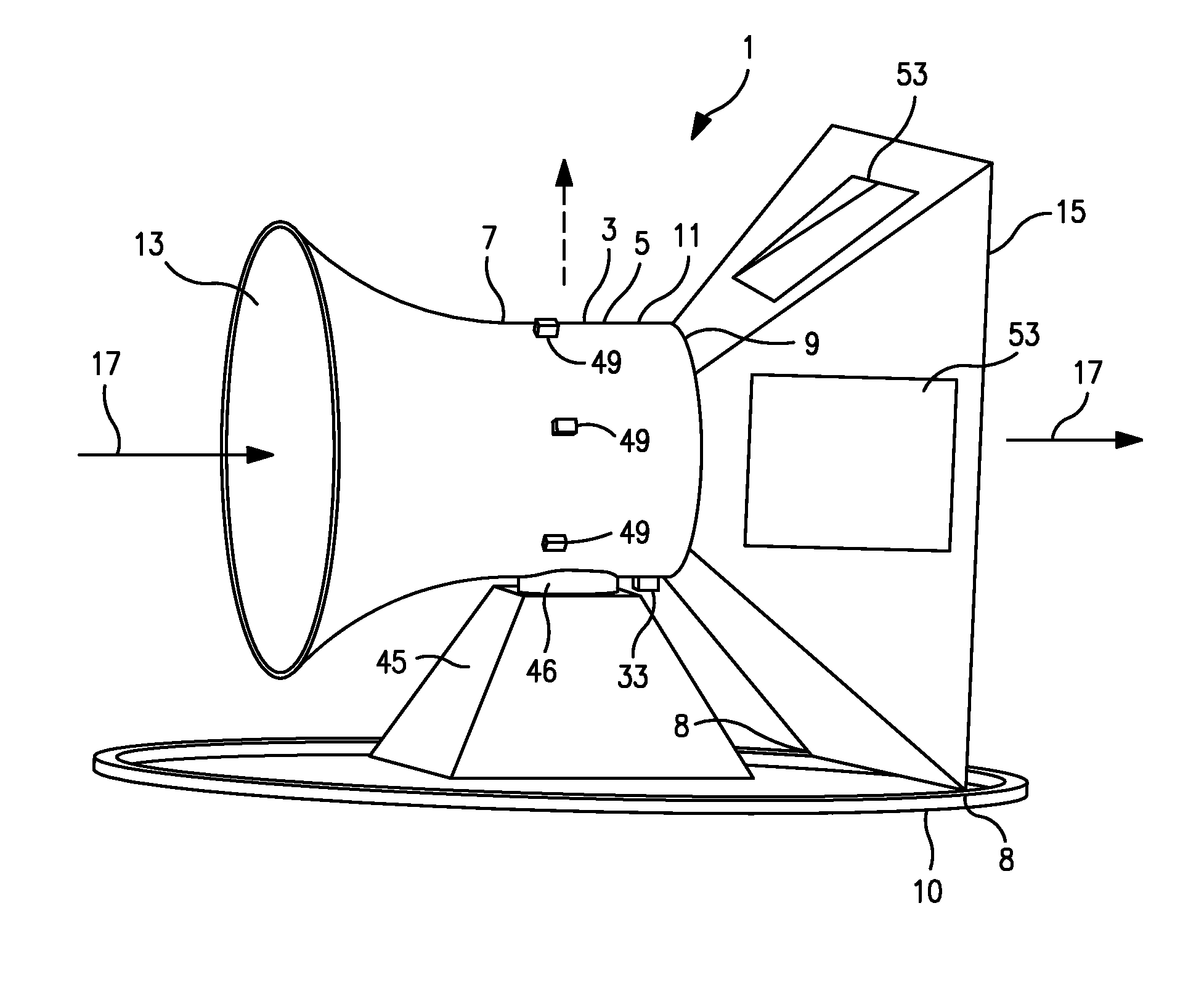
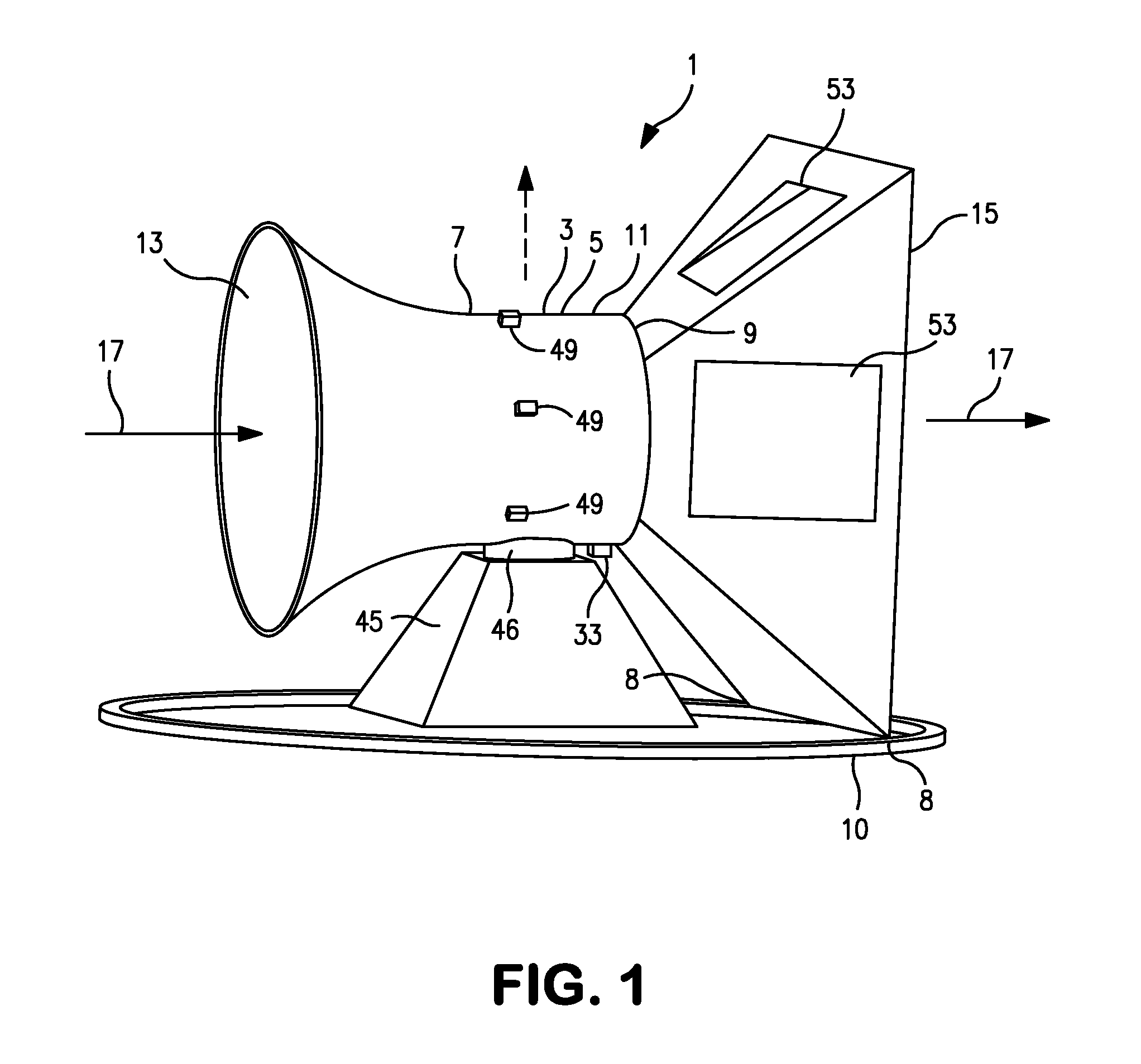
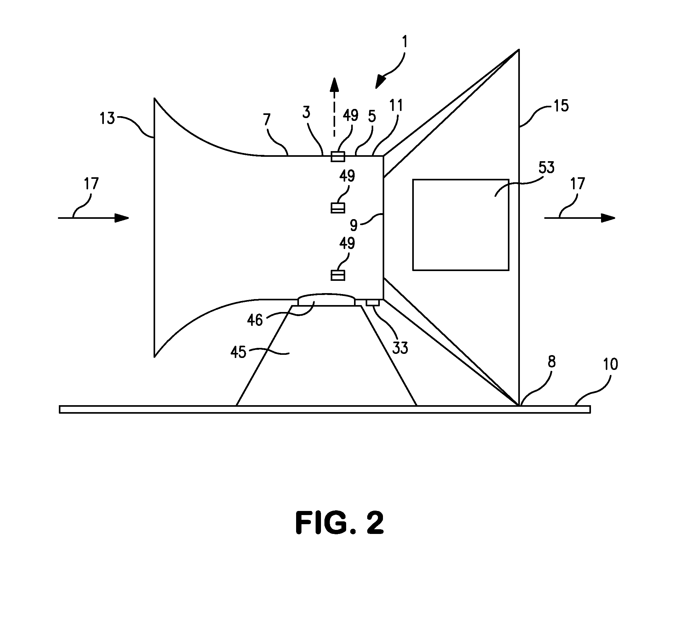
[0042]As illustrated in FIGS. 1-3, a synchronous induced wind power generation system 1 is provided that may be conveniently deployed in urban environments, such as on the tops of flat roofed buildings. In fact, this abundantly available urban area is one of the most advantageous locations for placement due to the higher ambient winds flowing over the roof. Further, the low noise level produced by the system 1 of the present invention during operation thereof is unobtrusive to occupants and neighbors. The electrical load of buildings can be partially met by the system of the present invention by converting the otherwise unused wind energy flowing across the roof into electrical power.

[0043]In particular, as shown in FIGS. 1-3, the present invention provides a synchronous induced wind power generation system 1 comprised generally of a turbine-generator section 3, a turbine-generator unit 21 disposed therein, a direction orientation means 45 such as support base or “lazy Susan” turnta...


PUM


Abstract

A synchronous induced wind power generation system is provided, which is comprised of a horizontally rotatable turbine-generator section that wind vanes into the prevailing wind direction. The turbine-generator section has a horizontally disposed turbine therein, and air induction shrouds at either end thereof, the anterior areas of the air induction shrouds having larger areas than the interior area of the turbine-generator section, so as to induce a large differential air pressure across the turbine. The turbine is directly coupled to a synchronous AC generator that is synchronized with an external power line in connection therewith, and directly generates synchronous AC power. Further, turbine magnetic brakes are employed 1) during synchronization with the electrical line, 2) to modulate turbine power, and 3) to protect against overspeed during high wind and loss of load.

Description

REFERENCE TO A RELATED APPLICATION[0001]This application is a CIP (continuation-in-part) patent application of copending U.S. patent application Ser. No. 12 / 713,140, filed Feb. 25, 2010, the contents of which are incorporated herein by reference.BACKGROUND OF THE INVENTION[0002]1. Field Of The Invention[0003]A synchronous induced wind power generation system is provided, which is comprised of a direct-coupled turbine-generator section on a horizontally rotatable gimbal that allows it to wind-vane into the prevailing wind. In particular, a wind powered synchronous electrical generation system is provided having a turbine-generator section with a horizontally disposed rotating shaft therein connecting the turbine to the generator, air inlet and air discharge shrouds formed thereon so as to induce higher differential air pressure across the turbine, turbine brakes to control the rotational speed of the turbine and the shaft power delivered to the synchronous generator, and a control sy...

Claims


Application Information

Patent Timeline
IPC IPC(8): H02P9/04F04D29/42
CPCF03D1/04H02K7/114H02K7/183Y02E10/725Y02B10/30Y02E10/72
Inventor SKALA, JAMES A.
Owner SKALA JAMES A
Why Eureka
Try Eureka