Acoustic sensor
- Summary
- Abstract
- Description
- Claims
- Application Information
AI Technical Summary
Benefits of technology
Problems solved by technology
Method used
Image

Examples
first embodiment
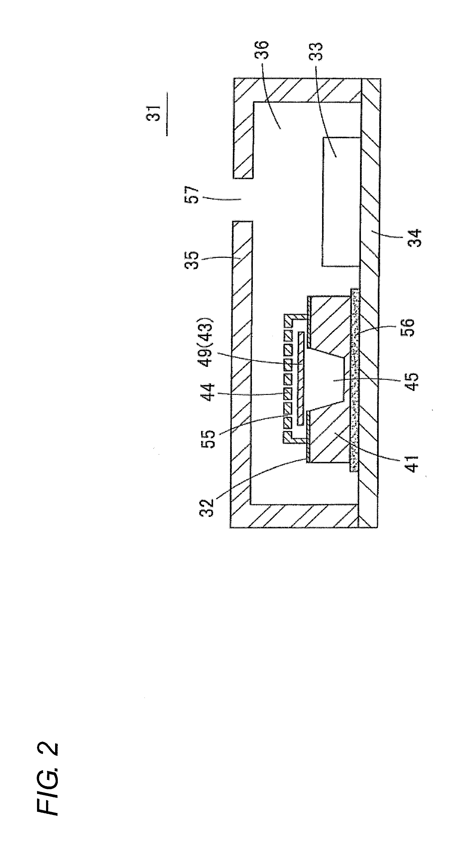
[0044]An acoustic sensor 31 according to a first embodiment of the present invention will be described below with reference to FIGS. 2 and 3. FIG. 2 is a schematic sectional view of the acoustic sensor 31. The acoustic sensor 31 mainly includes an acoustic sensing element 32 and a circuit element 33 (IC chip). Lower surfaces of the acoustic sensing element 32 and circuit element 33 are bonded to an upper surface of a base substrate 34, in which a wiring pattern is formed, by a thermosetting bonding agent (thermosetting resin bonding agent). The acoustic sensing element 32 and the circuit element 33 are covered with an electromagnetic shielding cover 35 joined to the upper surface of the base substrate 34, and the acoustic sensing element 32 and the circuit element 33 are accommodated in a space 36 that is formed by the base substrate 34 and the cover 35.
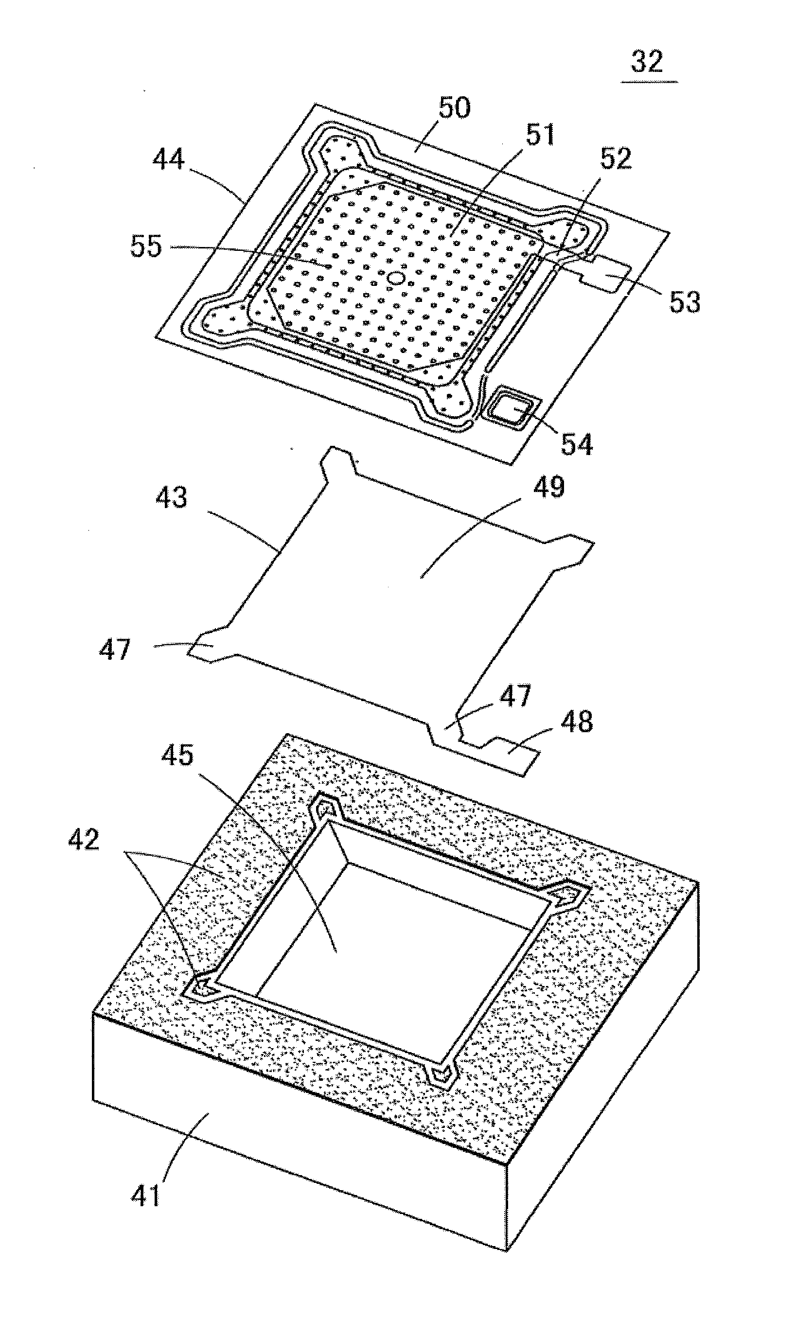
[0045]FIG. 3 is an exploded perspective view illustrating a structure of the acoustic sensing element 32. The acoustic sensing elem...
second embodiment
Modification of Second Embodiment
[0068]The back chamber 45 provided in the main substrate 41a may be formed into any shape as long as the back chamber 45 can be prepared. For example, the back chamber 45, in which an upper half is formed into a truncated-pyramid shape that is narrowed upward while a lower half is formed into an inverted truncated-pyramid shape that is narrowed downward, is formed in an acoustic sensor 68 according to a modification of the second embodiment as illustrated in FIG. 8.
Third Embodiment
[0069]FIG. 9 is a schematic sectional view illustrating an acoustic sensor 71 according to a third embodiment of the present invention. The sub-substrate 41b having the flat surface joined to the lower surface of the main substrate 41a is used in the acoustic sensor 61 of the second embodiment. On the other hand, in the acoustic sensor 71 of the third embodiment, a recess 45b is also formed in the sub-substrate 41b as illustrated in FIG. 10. That is, in the element substrat...
third embodiment
Modification of Third Embodiment
[0073]The through-hole 45a made in the main substrate 41a and the recess 45b provided in the sub-substrate 41b can be formed into various shapes in the third embodiment. For example, in an acoustic sensing element 72 illustrated in FIG. 12A, the recess 45b having the inverted truncated-pyramid shape illustrated in FIG. 12B is provided while communicated with the lower surface of the through-hole 45a having the prismatic shape. In an acoustic sensing element 73 illustrated in FIG. 13A, the recess 45b having the spherical shape illustrated in FIG. 13B is provided while communicated with the lower surface of the through-hole 45a having the prismatic shape.
[0074]Various modifications except those of FIGS. 12 and 13 can be made. The recesses 45b having the rectangular, inverted truncated-pyramid, and spherical shapes are provided in acoustic sensing elements 74 to 76 illustrated in FIGS. 14A to 14C while communicated with the lower surface of the through-h...
PUM
 Abstract
Description
Claims
Application Information
 - Generate Ideas
- Intellectual Property
- Life Sciences
- Materials
- Tech Scout
- Unparalleled Data Quality
- Higher Quality Content
- 60% Fewer Hallucinations
Browse by: Latest US Patents, China's latest patents, Technical Efficacy Thesaurus, Application Domain, Technology Topic, Popular Technical Reports.
© 2025 PatSnap. All rights reserved.Legal|Privacy policy|Modern Slavery Act Transparency Statement|Sitemap|About US| Contact US: help@patsnap.com