Multi-View Cargo Scanner

a cargo scanner and multi-view technology, applied in tomography, instruments, applications, etc., can solve the problems of increasing difficulty, difficulty in detecting contraband in break-bulk cargo, and difficulty in standard and advanced x-ray systems

Active Publication Date: 2011-08-25
RAPISCAN SYST INC (US)
View PDF18 Cites 63 Cited by
  • Summary
  • Abstract
  • Description
  • Claims
  • Application Information

AI Technical Summary

Benefits of technology

[0009]In one embodiment, the present invention is directed towards an inspection system for generating an increased number of scanning views of an object under inspection, comprising: a source for generating a high-energy electron beam; an electron beam steering system comprising a plurality of steering devices, for directing said electron beam to a corresponding plur

Problems solved by technology

The percentage of cargo to be inspected is increasing and, because of the currently manually intensive nature of inspections, so is the number of operators.
Standard and advanced X-ray systems have difficulty detecting contraband in break-bul

Method used


Image

  • Multi-View Cargo Scanner
  • Multi-View Cargo Scanner
  • Multi-View Cargo Scanner

Examples


first embodiment

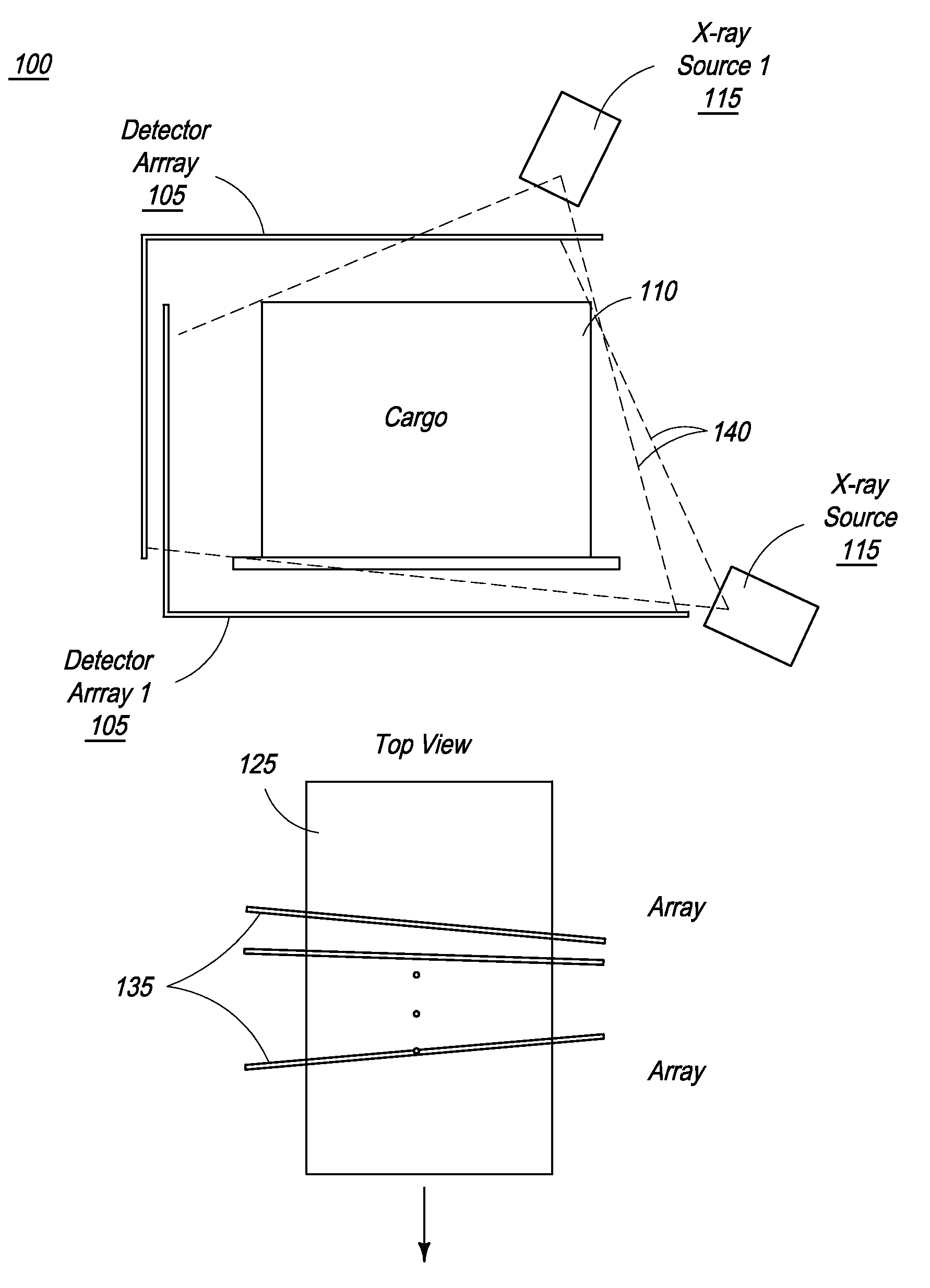
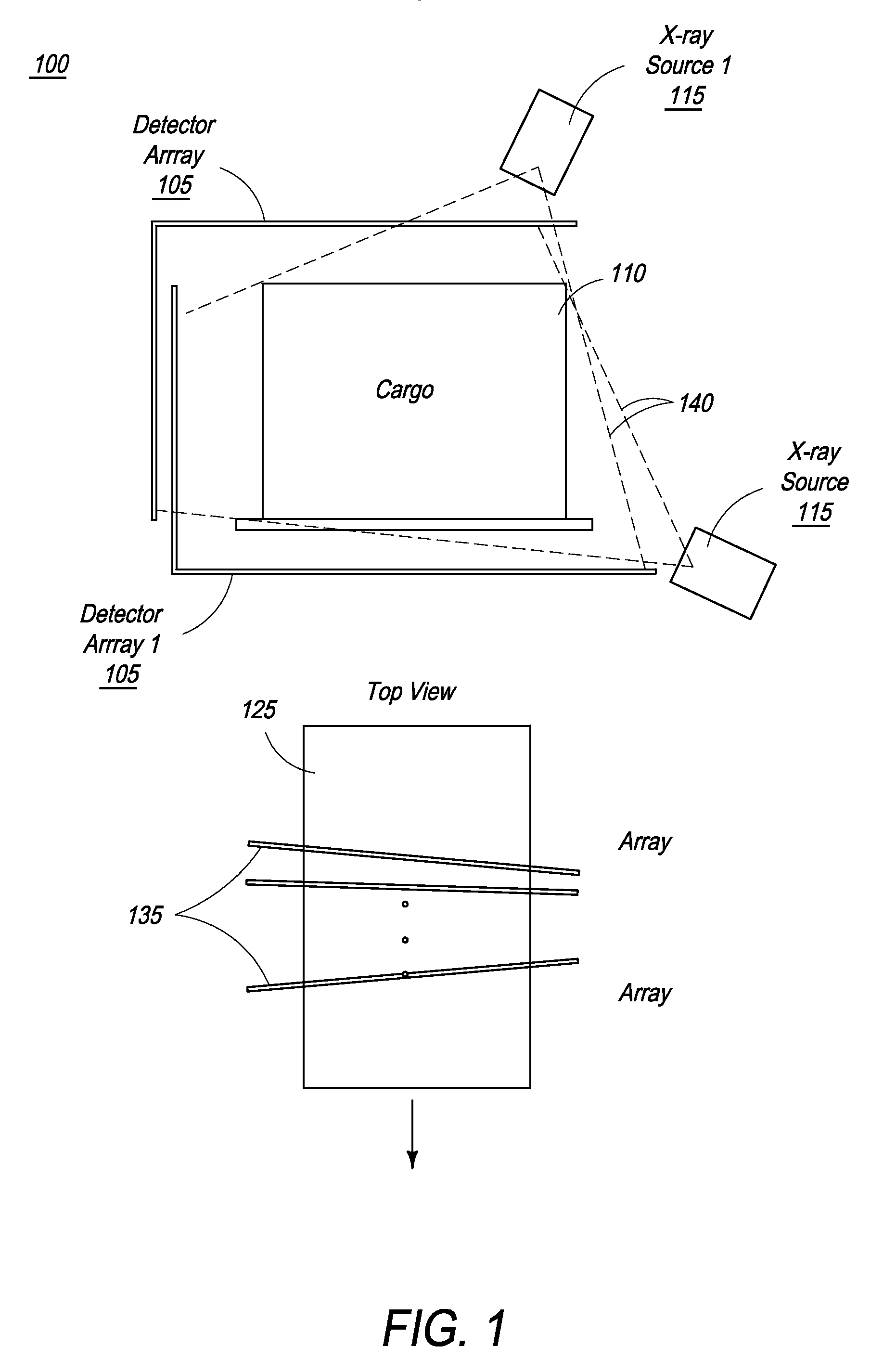
[0031]In a first embodiment, the present invention is directed toward an X-ray system comprising electron optics and / or beam transport systems that enable a single source to be implemented with multiple X-ray production targets, to yield a plurality of views. The leveraging of a single source with multiple X-ray production targets to yield multiple views reduces cost, power consumption and machine size.

[0032]In one embodiment, the source is a radiation source, such as a linear accelerator (linac) that is used to produce an electron beam. While the present invention is described with respect to use of a linac as the source, it should be understood that a number of sources can be used, for example, but not limited to such example, a particle accelerator (e.g. deuterons). If a particle accelerator is employed, the x-ray production targets are replaced with neutron production targets (e.g. deuterium gas) to produce neutrons.

[0033]In addition, when implemented in a CT system, a single so...

second embodiment

[0034]Therefore, in a second embodiment, the present invention is directed towards a synchronized conveyor and oscillating source / detector system whereby the degree and nature of the source / detector system's oscillation is tied to, and dependent upon, a step-wise progression of an object on a conveyor system. For example, the system can comprise a conveyor belt extending along a horizontal axis, around which a source / detector system can oscillate and generate a plurality of views from a plurality of angles, depending upon the source / detector position. The system then operates by moving an object on a conveyor system to a first linear position, stopping the conveyor system, initiating a scan by the source / detector system from a first arc position, completing the scan, moving the conveyor system (and therefore the object) to a second linear position, initiating a scan by the source / detector system from a second arc position, completing the scan, moving the conveyor system (and therefo...

third embodiment

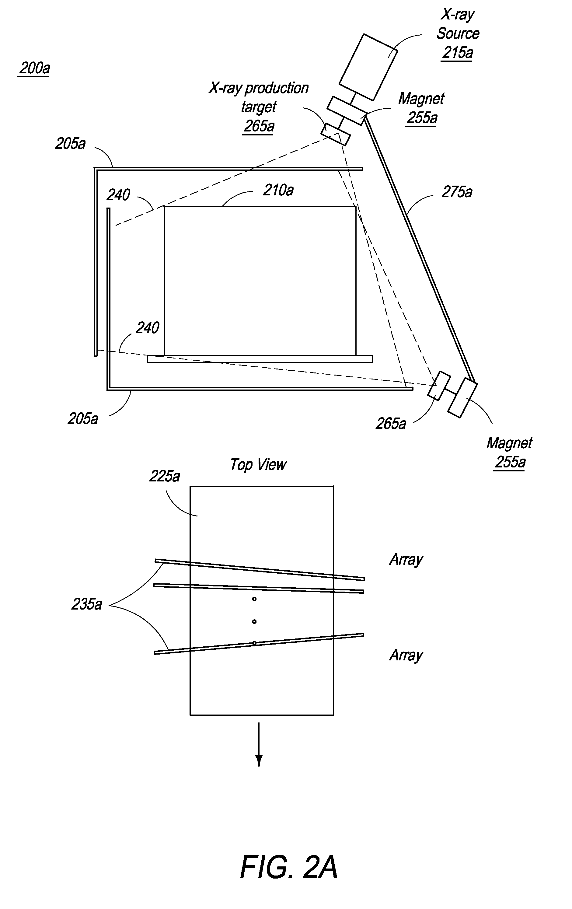
[0038]In a third embodiment, the present invention is directed towards a CT system that advantageously employs one source and does not require mechanical movement. Thus, the movement is achieved electronically rather than mechanically by rastering an electron beam generated from an X-ray source along an approximated arc using a combination of magnets and quadrupoles. The electron beam is directed toward at least one X-ray production target to produce a rotating X-ray beam (stationary gantry), while the object is translated at a constant speed.

[0039]All the above mentioned embodiments can be used in different configurations such in a fixed site, gantry or mobile configurations, further including a conveyor mechanism or other transport mechanism.

[0040]The present invention is directed towards multiple embodiments. The following disclosure is provided in order to enable a person having ordinary skill in the art to practice the invention. Language used in this specification should not b...


PUM


Abstract

The present invention provides a multi-view X-ray inspection system. In one embodiment, a beam steering mechanism directs the electron beam from an X-ray source to multiple production targets which generate X-rays for scanning which are subsequently detected by a plurality of detectors to produce multiple image slices (views). The system is adapted for use in CT systems. In one embodiment of a CT system, the X-ray source and detectors rotate around the object covering an angle sufficient for reconstructing a CT image and then reverse to rotate around the object in the opposite direction. The inspection system, in any configuration, can be deployed inside a vehicle for use as a mobile detection system.

Description

CROSS-REFERENCE TO RELATED APPLICATIONS[0001]The present invention relies on U.S. Provisional Patent Application No. 61 / 296,080, of the same title, and filed on Jan. 19, 2010, for priority, which is hereby incorporated by reference.FIELD OF THE INVENTION[0002]The present invention is directed to a multi-view, multi-energy cargo scanner and, more specifically, methods and systems of cost-effectively increasing the number of scanning views of an object or cargo under inspection, thereby improving estimations of the density and atomic number of the cargo contents for enhanced detection of contraband and other materials of interest.BACKGROUND OF THE INVENTION[0003]Cargo containers need to be inspected at ports and other points of entry or transportation for contraband such as explosives, narcotics, currency, chemical and nuclear weapons, and for cargo-manifest verification. Detection of contraband with both high detection rates and low false alarm rates is a daunting task, as these mate...

Claims


Application Information

Patent Timeline
IPC IPC(8): G01N23/04
CPCG01V5/0016G01V5/005G01T3/00A61B6/03
Inventor BENDAHAN, JOSEPH
Owner RAPISCAN SYST INC (US)
Why Eureka
Try Eureka