Bias control in an optical modulator and transmitter

a technology of optical modulators and bias control, which is applied in the direction of multiplex communication, electrical apparatus, and wavelength-division multiplex systems, can solve the problems that the control system of optical modulators of the prior art is not adapted to control modulators operating at different wavelengths

Active Publication Date: 2011-08-25
LUMENTUM OPERATIONS LLC
View PDF18 Cites 44 Cited by
  • Summary
  • Abstract
  • Description
  • Claims
  • Application Information

AI Technical Summary

Benefits of technology

[0016](e) adjusting the second bias signal, so as to lessen a difference between the operational peak-to-peak optical power variation measured in step (d) and the target peak-to-peak optical power variation stored in step (c), thereby obtaining the pre-determined value of the performance parameter without having to re-measure the performance parameter,

Problems solved by technology

Optical modulator control systems of the prior art are not adapted to control a modulator operating at different wavelengths.

Method used


Image

  • Bias control in an optical modulator and transmitter
  • Bias control in an optical modulator and transmitter
  • Bias control in an optical modulator and transmitter

Examples


Embodiment Construction

[0030]While the present teachings are described in conjunction with various embodiments and examples, it is not intended that the present teachings be limited to such embodiments. On the contrary, the present teachings encompass various alternatives, modifications and equivalents, as will be appreciated by those of skill in the art.

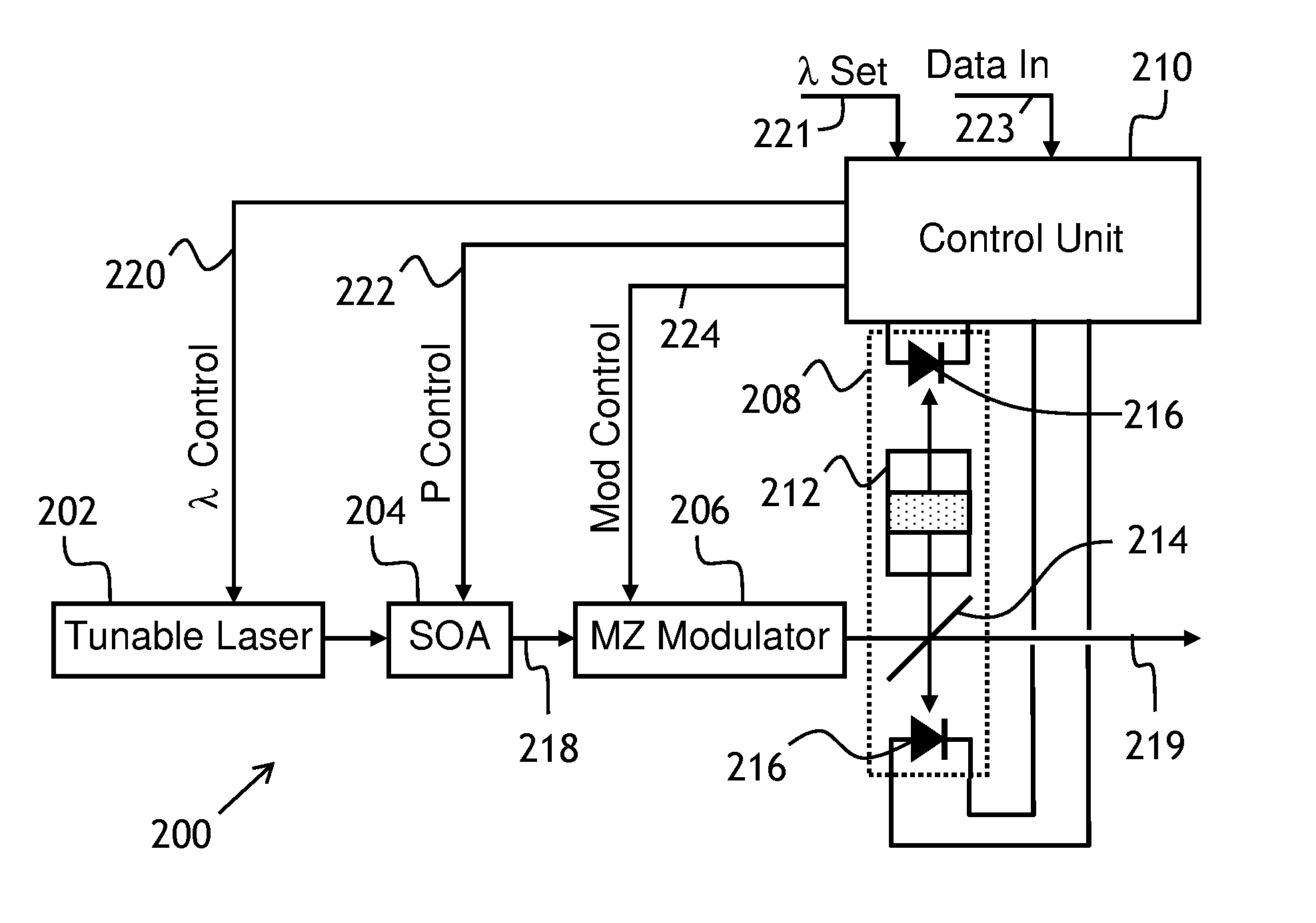
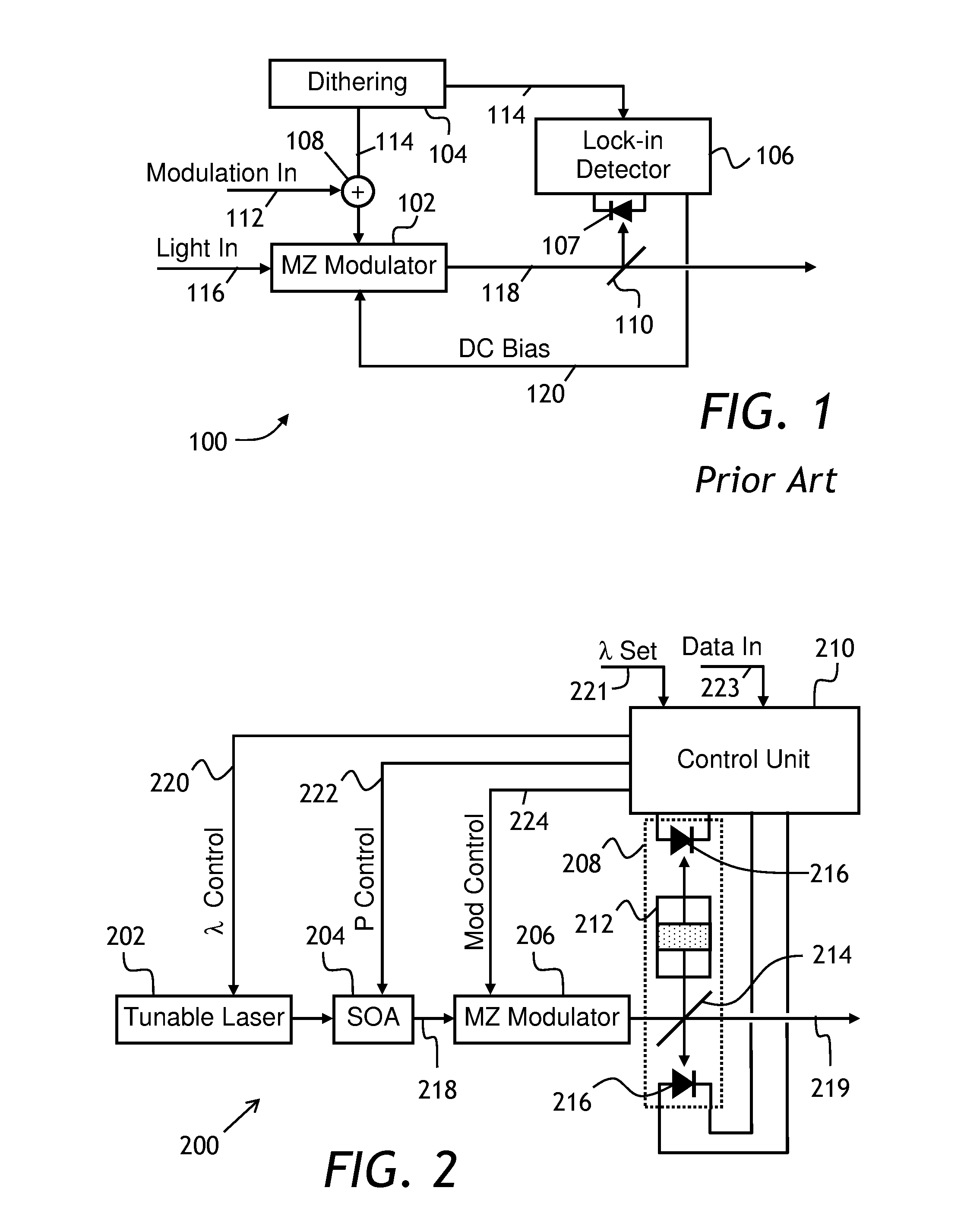
[0031]Referring to FIG. 2, a tunable transmitter 200 includes a tunable laser 202, a semiconductor optical amplifier (SOA) 204, a Mach-Zehnder (MZ) modulator 206, a wavelength locker 208, and a control unit 210. The wavelength locker 208 has a Fabry-Perot interferometer or etalon 212, a beamsplitter 214, and two photodetectors 216, preferably photodiodes, for detecting an optical signal reflected from and transmitted through the Fabry-Perot interferometer 212. In operation, the control unit 210 provides a wavelength control signal 220 for tuning the wavelength of the tunable laser 202 to a wavelength set at a wavelength input 221, a power control signal 2...


PUM


Abstract

An apparatus and method for controlling bias in an optical modulator is disclosed. The method is particularly applicable to controlling multi-wavelength modulators and wavelength-tunable transmitters. At a calibration stage, a desired optical performance of the modulator is achieved, and an amplitude of a peak-to-peak variation of the output optical signal at a pre-determined amount of dither is stored in a memory as a reference. At operating stage, a controller of the optical modulator adjusts a bias voltage of the modulator until the measured peak-to-peak optical signal variation matches the reference value stored at the calibration stage. For multi-wavelength modulators and tunable transmitters, the calibration is repeated at each wavelength, and corresponding peak-to-peak optical signal variations are stored in the memory.

Description

CROSS-REFERENCE TO RELATED APPLICATIONS[0001]The present invention claims priority from U.S. Patent Application No. 61 / 307,741 filed Feb. 24, 2010 which is incorporated herein by reference for all purposes.TECHNICAL FIELD[0002]The present invention relates to optical modulators and transmitters, and in particular to controlling optical modulators and wavelength-tunable transmitters used in optical communications.BACKGROUND OF THE INVENTION[0003]Optical modulators are used in optical communication systems to modulate an optical signal with an electrical signal. The electrical signal can have a high frequency, for example a few gigahertz. The modulated optical signal is propagated over large distances in an optical fiber. At the receiver end, the signal is detected using a photodetector, and the electrical signal is restored for further processing or transmission.[0004]Presently, wavelength-tunable transmitters find an increasing application in optical networking systems capable of pr...

Claims


Application Information

Patent Timeline
Patent Type & Authority Applications(United States)
IPC IPC(8): H04B10/04
CPCH04B10/572H04B10/50575
Inventor ZHOU, YUXINLIM, HOCK GIN
Owner LUMENTUM OPERATIONS LLC
Why Eureka
Try Eureka