
Image forming apparatus and electrophotographic cartridge

Active Publication Date: 2011-08-25
MITSUBISHI CHEM CORP
View PDF34 Cites 22 Cited by
  • Summary
  • Abstract
  • Description
  • Claims
  • Application Information

AI Technical Summary

Benefits of technology

[0096]For the percentage by number (Dns) of toner particles, the particle diameter is defined to be from 2.00 μm to 3.56 and the reason is as follows. The lowermost limit is the detection limit of the particle sizer used in measuring the toner particle size in the invention; and the uppermost limit is the critical value of the effect obtained from the results in Examples. Specifically, when the percentage by number of toner particles having a particle size larger than 3.56 μm is employed, then the toner capable of exhibiting the effect of the invention could not be clearly differentiated from the other toner not exhibiting the effect.
[0097]Regarding the relationship between Dv50 and Dns, preferably, the toner satisfies Dns≦0.110EXP(19.9 / Dv50) from the viewpoint of the above-mentioned effect of the invention.
[0098]On the other hand, from the viewpoint of securing good producibility with good production yield, the relationship between Dv50 and Dns satisfies the following:0.0517EXP(22.4 / Dv50)≦Dns  (3′)
[0099]Preferably, the toner for use in the invention has Dns of 6% or less by number, as capable of providing better-quality images not soiling the image forming apparatus. Regarding the combination of the preferred particle size region of Dv50, for example, “Dv50 of 4.5 μm or more” and the condition of “Dns of 6% or less by number”, more preferably, both the two are satisfied simultaneously. Within the range, the toner can provide high-quality images not detracting from the production yield from the viewpoint of the producibility, and does not soil the image forming apparatus; and accordingly, there may be provided a toner that hardly brings about “selective development”.<Regarding (4)>
[0100]The number variation coefficient of the toner in the invention is 24.0% or less, preferably 22.0% or less, more preferably 20.0% or less, even more preferably 19.0% or less. In general, a higher number variation coefficient means a broader electrostatic charge distribution, therefore as the case may be, causing image defects owing to charging failure. In addition, the toner of the type may adhere to and soil toner-related members and may scatter and soil them. Accordingly, the number variation coefficient is preferably smaller. On the other hand, from the industrial viewpoint, the number variation coefficient is preferably larger than 0%, more preferably 5% or more.
[0101]The number variation coefficient (%) is measured according to the method described in the section of Examples, and is defined as one measured in that manner.

Problems solved by technology

Particularly, as the developer to be used in a case where latent images on a latent image substrate constituting an image forming apparatus are line images of 100 μm or less (about 300 dpi or more), a conventional toner having a large particle size is usually poor in reproducibility of such fine lines, whereby the sharpness of line images has not yet been sufficient.
When the outer diameter of appliances is reduced, then cleaning them with a cleaning blade would become difficult therefore bringing about troubles of cleaning failure, filming, etc.
In addition, reduction in the particle size of toner wound promote the tendency, and therefore, mismatching between toner and photoreceptor is an important subject.
Further, in a case where a linear pressure of a cleaning blade is increased for bettering the cleaning capability thereof, there may occur a problem in that the printer may produce an unpleasant noise and abnormal noise.

Method used


Image

  • Image forming apparatus and electrophotographic cartridge
  • Image forming apparatus and electrophotographic cartridge
  • Image forming apparatus and electrophotographic cartridge

Examples


production example 1

[0521]100 parts of a polyarylate resin having the following repeating structure (resin 1, viscosity-average molecular weight 40,000), 80 parts of a charge-transporting substance, CTM1 of the following formula (mixture of two types of cis forms, blend ratio 1 / 1) and 8 parts of an antioxidant, compound of the following formula (AOX1), and 0.10 parts of dimethylpolysiloxane (Shin-etsu Chemical's KF96-10CS) were dissolved in 640 parts of a mixed solvent of tetrahydrofuran / toluene (8 / 2 by weight) to prepare a charge transport layer-forming coating liquid.

production example 2

[0522]A charge transport layer-forming coating liquid was prepared in the same manner as in Production Example 1, except that the amount of the resin 1 used in the charge transport layer-forming coating liquid in Production Example 1 was changed to 50 parts and 50 parts of a polycarbonate resin having the following repeating structure (resin 2, viscosity-average molecular weight 40,000) was additionally used.

production example 3

[0523]A charge transport layer-forming coating liquid was prepared in the same manner as in Production Example 1, except that Unitika's U-Polymer (resin 3) was used in place of the polyarylate resin (resin 1) used in the charge transport layer-forming coating liquid in Production Example 1 and, as the solvent, chlorobenzene was used in place of the mixed solvent of tetrahydrofuran / toluene.


PUM

PropertyMeasurementUnit
Lengthaaaaaaaaaa
Energyaaaaaaaaaa
Massaaaaaaaaaa

Abstract

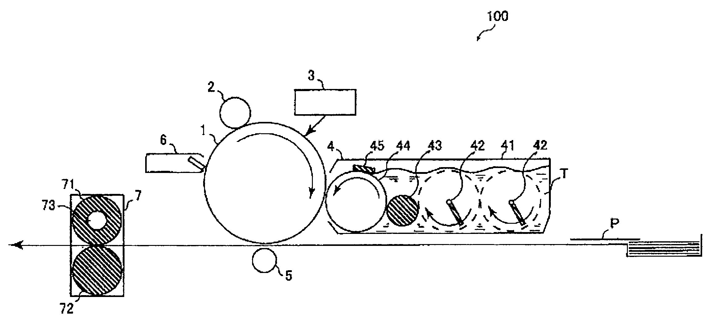
The invention is to provide an image forming apparatus and an electrophotographic cartridge, which are free from problems of cleaning failure, filming, soiling, residual images (ghosts), fogging, density reduction, noise and the like and which can provide high-definition images even when a toner having a small particle size and having a high degree of circularity is used and even when a photoreceptor having a small outer diameter is used. An image forming apparatus comprising: an electrophotographic photoreceptor containing a conductive support and a photosensitive layer on the conductive support, a charging unit for charging the electrophotographic photoreceptor, an imagewise exposing unit for imagewise exposing the charged electrophotographic photoreceptor to form an electrostatic latent image thereon, a developing unit for developing the electrostatic latent image with a toner, and a transferring unit for transferring the toner from the electrophotographic photoreceptor to a receiving unit, wherein the outer diameter of the electrophotographic photoreceptor is 20 mm or less, the photosensitive layer contains a polyarylate resin, and the toner satisfies the specific requirements (1) and (2).

Description

FIELD OF THE INVENTION[0001]The present invention relates to an image forming apparatus and an electrophotographic cartridge for use in copying machines, printers, etc.BACKGROUND OF THE INVENTION[0002]In recent years, applications of image forming apparatus such as electrophotographic copying machines and others have been expanding, and there has been an increasing demand in the market for a higher level of image quality. Particularly, with respect to office documents and others, in addition to the development of image copying techniques and latent image-forming techniques at the time of inputting, also at the time of outputting, the types of hieroglyphic characters have become richer and more refined, and due to dissemination and development of presentation software, reproducibility of latent images of extremely high quality is desired so that there will be few defects or unsharpness in printed images. Particularly, as the developer to be used in a case where latent images on a lat...

Claims


Application Information

Patent Timeline
IPC IPC(8): G03G21/18G03G15/00
CPCG03G5/04G03G5/043G03G5/0525G03G5/0542G03G5/0567G03G5/1473G03G2215/0604G03G9/0827G03G9/0906G03G9/0926G03G21/0005G03G2215/00957G03G9/0819G03G5/047G03G5/056G03G5/0618G03G5/0629G03G9/08711G03G9/0904G03G9/09321G03G9/09364G03G9/09385G03G9/09392G03G21/0011
Inventor MIZUSHIMA, TADASHIFUJII, AKITERUSHODA, TAKAYUKI
Owner MITSUBISHI CHEM CORP
Features
  • Generate Ideas
  • Intellectual Property
  • Life Sciences
  • Materials
  • Tech Scout
  • Unparalleled Data Quality
  • Higher Quality Content
  • 60% Fewer Hallucinations
Learn More