Method for operating a blast furnace and blast furnace installation

a technology for blast furnaces and installation methods, applied in blast furnaces, climate sustainability, metal processing, etc., can solve the problems of flash gasification or partial devolatisation of volatile carbon containing materials, and achieve the effect of improving blast furnace installation

Inactive Publication Date: 2011-09-01
PAUL WURTH SA
View PDF4 Cites 15 Cited by
  • Summary
  • Abstract
  • Description
  • Claims
  • Application Information

AI Technical Summary

Benefits of technology

[0006]The invention provides an improved method for operating a blast furnace. The invention further provides an improved blast furnace installation.

Problems solved by technology

Indeed, when the volatile carbon containing material enters the reformer unit into which the recovered top gas is fed, the volatile carbon containing material is subjected to flash gasification, or partial devolatisation, due to the high temperature reigning in the reformer unit.

Method used


Image

  • Method for operating a blast furnace and blast furnace installation
  • Method for operating a blast furnace and blast furnace installation

Examples


Embodiment Construction

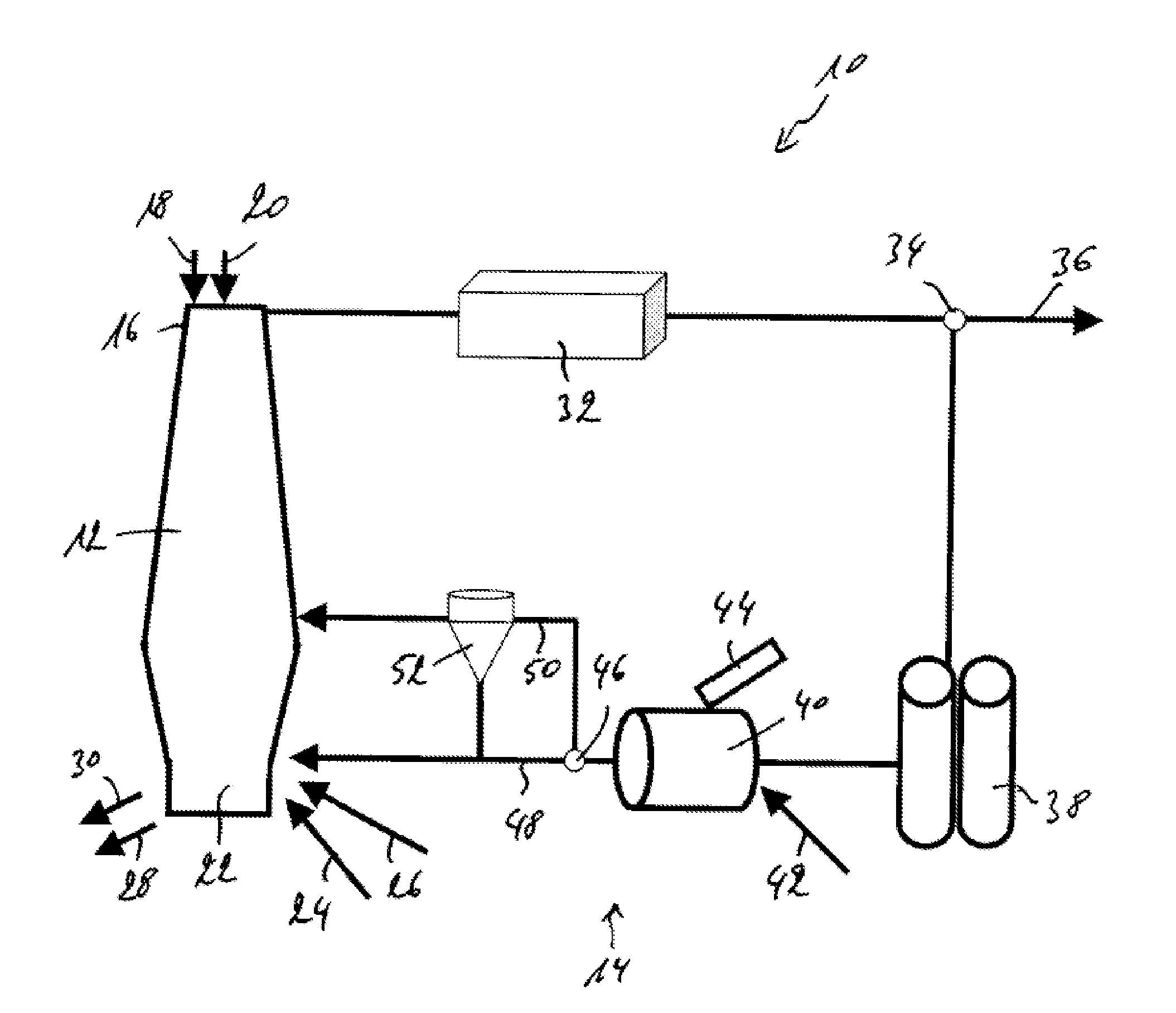
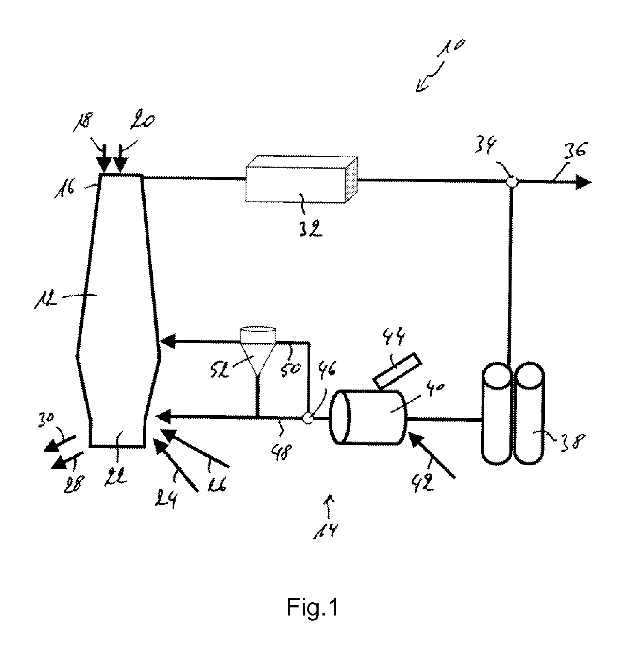
[0027]FIG. 1 generally shows a blast furnace installation 10 comprising a blast furnace 12 and a top gas recycling installation 14. The top end 16 of the blast furnace 12 generally receives a charge of coke 18 and a charge of ore 20, while the bottom end 22 of the blast furnace 12 generally receives fuel 24 and oxygen 26. At the bottom end 22, pig iron 28 and slag 30 is extracted from the blast furnace 12. The operation of the blast furnace itself is well known and will not be further described herein.

[0028]The top gas recycling installation 14 comprises means for recovering top gas from the blast furnace, for treating the recovered top gas and for injecting the treated top gas back into the blast furnace. The top gas recycling installation 14 is more closely described herebelow.

[0029]The blast furnace top gas is recovered from the top end 16 of the blast furnace 12 and first fed through a gas cleaner unit 32, wherein the amount of dust or foreign particles is reduced.

[0030]After pa...


PUM

PropertyMeasurementUnit
temperatureaaaaaaaaaa

Abstract

A method for operating a blast furnace and a corresponding blast furnace, the method including recovering top gas from the blast furnace, submitting at least a portion of the top gas to a recycling process, and feeding the recycled top gas back into the blast furnace, where the recycling process includes feeding the recovered top gas to a reformer unit, feeding volatile carbon containing material to the reformer unit, proceeding to flash gasification of the volatile carbon containing material in the reformer unit, at a temperature between 1100 and 1300° C., and thereby producing devolatised carbonaceous material and synthesis, and allowing the devolatised carbonaceous material and synthesis gas to react with the recovered top gas.

Description

TECHNICAL FIELD[0001]The present invention generally relates to a method for operating a blast furnace, in particular for recycling top gas. The invention further relates to a blast furnace installation, in particular comprising a top gas recycling installation.BACKGROUND[0002]For many years, attempts have been made to reduce CO2 emissions from blast furnaces so as to contribute to the general worldwide reduction of CO2 emissions.[0003]Mainly in order to reduce the amount of coke used, a suggestion was made to recover the top gas from the blast furnace and to inject it back into the blast furnace to aid the reduction process. Devices have been proposed for separating the recovered top gas into a CO2 rich gas for use or storage elsewhere and a CO2 poor gas for injection back into the blast furnace so as to allow the reduction of coke.[0004]Top gas can be reformed by reducing its CO2 content, e.g. by a method wherein fossil fuel is added to the top gas to partially convert carbon diox...

Claims


Application Information

Patent Timeline
Patent Type & Authority Applications(United States)
IPC IPC(8): C21B7/22C21C5/40
CPCC10B49/02C21B5/06Y02E50/14C21B2100/02C21B2100/04C21B7/002Y02P10/122C21B2100/22Y02E50/10Y02P10/25C10B53/02C21B7/00
Inventor ROTH, JEAN-LUCSIMOES, JEAN-PAUL
Owner PAUL WURTH SA
Why Eureka
Try Eureka