Optical fiber and optical communication system including same

Active Publication Date: 2011-09-01
SUMITOMO ELECTRIC IND LTD
View PDF1 Cites 16 Cited by
  • Summary
  • Abstract
  • Description
  • Claims
  • Application Information

AI Technical Summary

Benefits of technology

[0019]The optical communication system according to the present invention can construct an optical communication system having a repeater span of 80 km or more (a long repeater span) by using a plurality of first optical fibers and a plurality of second optical fibers. In this case, a plurality of first optical fibers are disposed at two or more locations in the repeater span of 80 km or more. A plurality of second optical fibers are connected to the first optical fibers at four or more locations in the repeater span. Each of the plurality of second optical fibers has an effective area Aeff of 85 μm2 or less at the wavelength of 1550 nm. The plurality of second optical fibers include at least those disposed at both ends of the repe

Problems solved by technology

When the effective area Aeff of the transmission optical fiber is much larger than that of optical fibers at both ends of the devices or the other transmission optical fibers, the splice loss becomes greater, thereby deteriorating the OSNR of the optical communication system as

Method used


Image

  • Optical fiber and optical communication system including same
  • Optical fiber and optical communication system including same
  • Optical fiber and optical communication system including same

Examples


Embodiment Construction

present embodiment obtained when changing the Young's modulus of coating resins and the effective area Aeff;

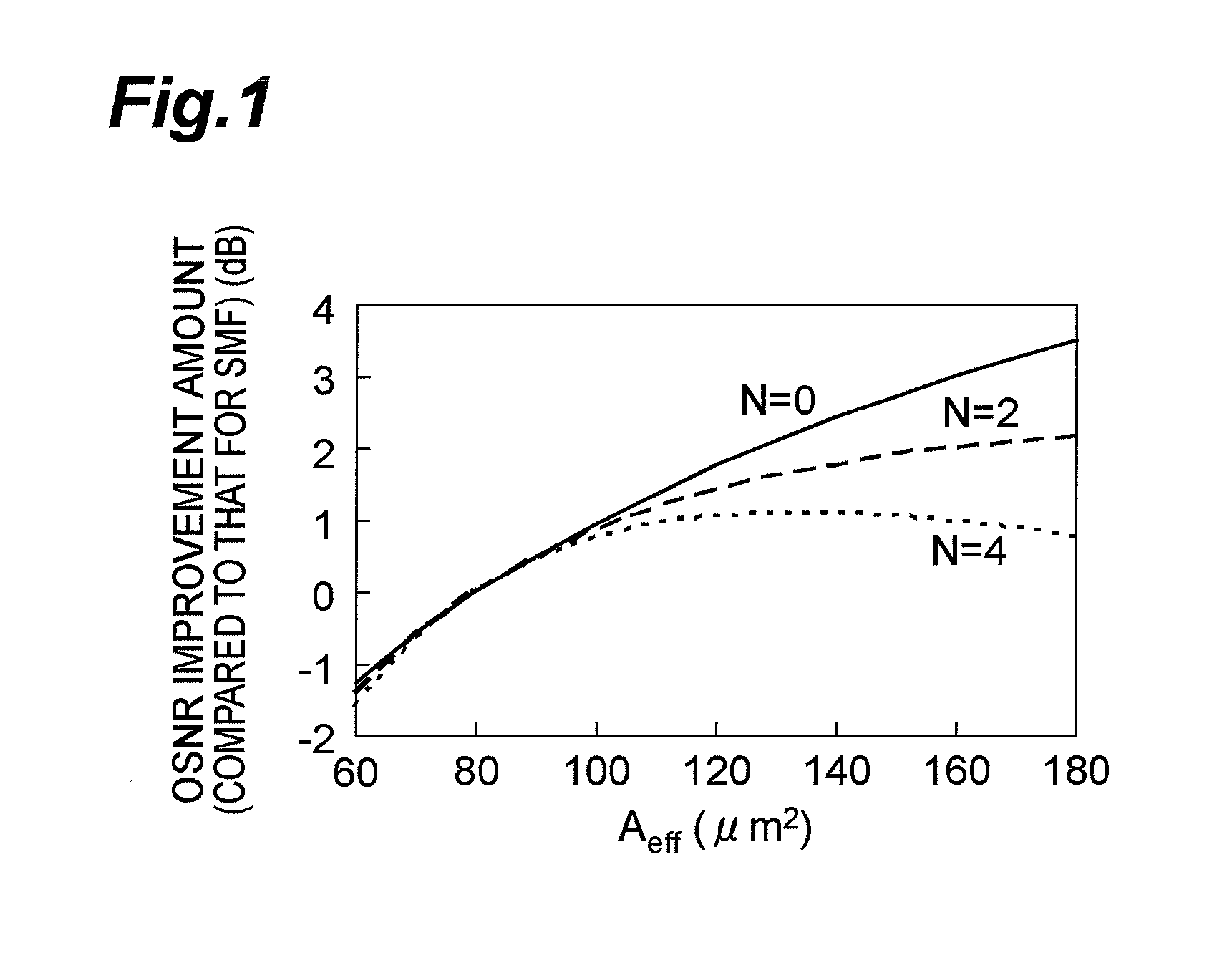
[0029]FIGS. 7A to 7C are graphs showing, in terms of the relationship between the effective area Aeff and transmission loss, the amount of improvement in OSNR over a single-mode fiber (SMF) caused by differences in splicing states in a repeater span;

[0030]FIG. 8 is a flowchart for explaining actions for determining the structure of the optical fiber according to the present embodiment; and

[0031]FIGS. 9A and 9B are views showing the structures of respective embodiments of the optical communication system according to the present invention.

DESCRIPTION OF THE PREFERRED EMBODIMENTS

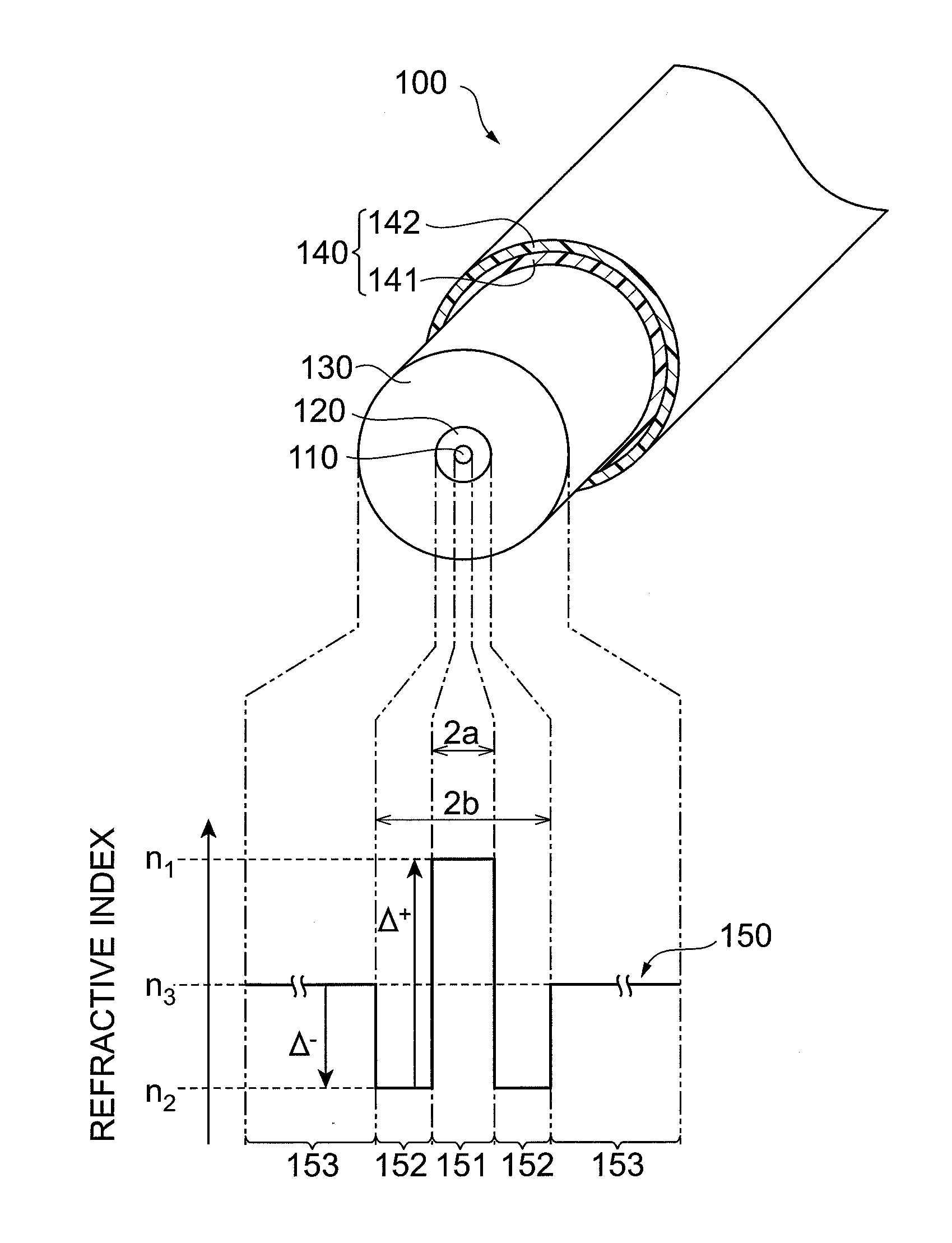
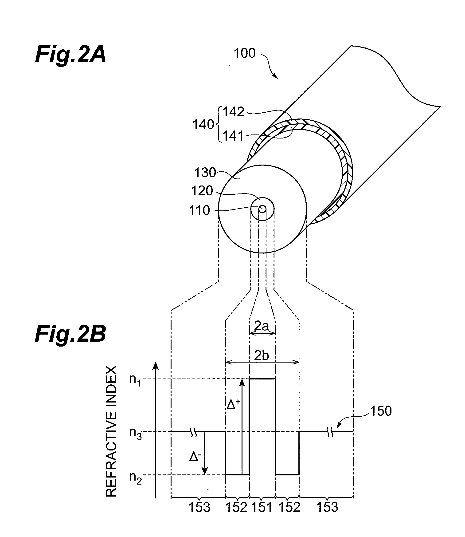
[0032]In the following, embodiments of the optical fiber and optical communication system according to the present invention will be explained in detail with reference to FIGS. 1, 2A, 2B, 3 to 6, 7A to 7C, 8, 9A, and 9B. In the description of the drawings, identical or corresponding components are design...


PUM


Abstract

The invention relates to an optical fiber employable in an optical communication system using Raman amplification and adapted to improve OSNR and suppress bending loss at the same time, and the like. The optical fiber is a silica-based optical fiber having a depressed refractive index profile constituted by at least a core, an inner cladding having a low refractive index, and an outer cladding, an effective area Aeff of 110 μm2 or more at the wavelength of 1550 nm, and a fiber cutoff wavelength λC of 1.3 μm or more but 1.53 μm or less. The depressed refractive index profile is designed such that the ratio Ra(=2b/2a) of the diameter of the inner cladding to the diameter of the core is 2.5 or more but 3.5 or less and that the relative refractive index difference Δ of the inner cladding with respect to the outer cladding is at least the relative refractive index difference Δmin where the bending loss at the wavelength for use is minimized but not exceeding (Δmin+0.06) %.

Description

BACKGROUND OF THE INVENTION[0001]1. Field of the Invention[0002]The present invention relates to an optical fiber which improves the optical signal-to-noise ratio (hereinafter referred to as OSNR) in a wavelength division multiplexing optical communication system using Raman amplification over a long repeater span, and an optical communication system employing such an optical fiber.[0003]2. Related Background Art[0004]Recently, in optical communication systems, techniques for compensating for waveform distortions resulting from dispersions by using digital signal processing (DSP) such as digital coherent receiver technology have been advancing in receivers. This has rapidly been increasing demands for improving the OSNR rather than dispersion values in optical transmission lines. For increasing the transmission rate without deteriorating the signal quality at a fixed repeater span in a communication system, the OSNR must be raised. For doubling the transmission rate, for example, it...

Claims


Application Information

Patent Timeline
IPC IPC(8): G02B6/26
CPCG02B6/02019G02B6/02395G02B6/03627
Inventor YAMAMOTO, YOSHINORIHIRANO, MASAAKI
Owner SUMITOMO ELECTRIC IND LTD
Why Eureka
Try Eureka