Microscope System, Specimen Observation Method, and Computer Program Product

Active Publication Date: 2011-09-01
EVIDENT CORP +1
View PDF10 Cites 51 Cited by
  • Summary
  • Abstract
  • Description
  • Claims
  • Application Information

AI Technical Summary

Problems solved by technology

However, there is a problem that the observation by the fluorescent labeling cannot be performed easily because the specimen cannot be preserved for a long period of time, the diagnosis takes a long time, and a dedicated dark room is required.
In addition, there i

Method used


Image

  • Microscope System, Specimen Observation Method, and Computer Program Product
  • Microscope System, Specimen Observation Method, and Computer Program Product
  • Microscope System, Specimen Observation Method, and Computer Program Product

Examples


first embodiment

[0062]In a first embodiment, the presence or absence of a target molecule located (expressed) on a predetermined cell component is set as an extraction condition, and a portion in a specimen that matches the extraction condition is extracted as a target portion. Here, the cell component is a collective name of cell nucleus, cell membrane, cytoplasm, and the like that are cell constituent elements constituting a cell.

[0063]First, a specimen to be observed and diagnosed (hereinafter referred to as “target specimen”) will be described. The target specimen is a multistained specimen that is multistained with a plurality of dyes. More specifically, the target specimen is a specimen on which the morphological observation staining for observing the morphology of the specimen and the molecule target staining for checking an expression of molecule information are performed, and includes a specimen used for a tissue diagnosis and a specimen used for a cytological diagnosis. In the cytological...

second embodiment

[0262]In a second embodiment, a cell is recognized on the basis of an identification result of a cell component, and normality / abnormality thereof is determined. In the description below, it is assumed that cell component identification staining for identifying three cell components, which are cell nucleus, cell membrane, and cytoplasm, is performed on the target specimen S, and the three components are identified.

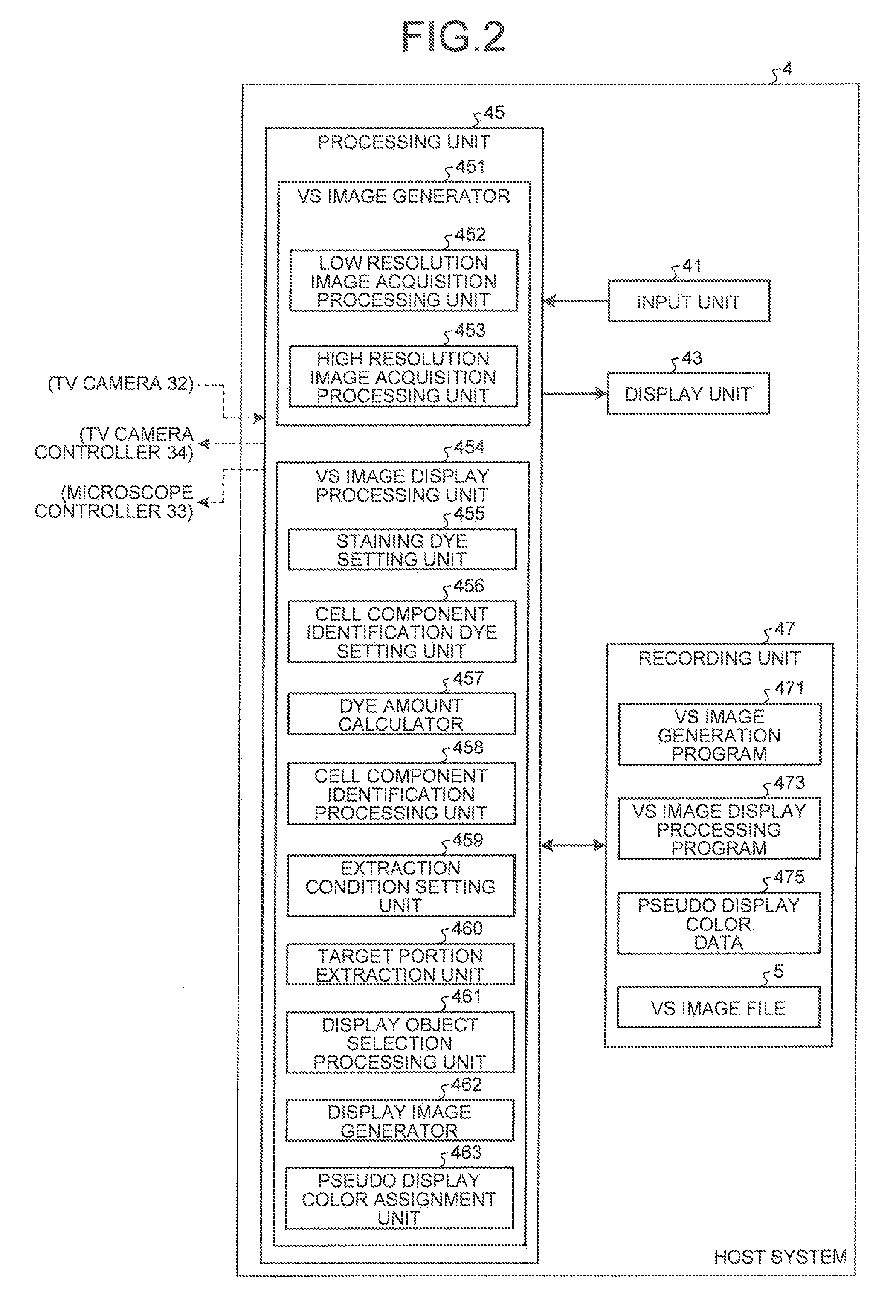
[0263]FIG. 34 is a diagram showing main functional blocks of a host system 4b according to the second embodiment. The same reference numerals are given to the same components as those described in the first embodiment, As shown in FIG. 34, the host system 4b included in a microscope system according to the second embodiment includes the input unit 41, the display unit 43, a processing unit 45b, a recording unit 47b, and the like.

[0264]A VS image display processing unit 454b in the processing unit 45b includes a staining dye setting unit 455, a cell component identification...

third embodiment

[0298]As described above, it is possible to calculate statistics such as the number of positive cells and the rate of positive cells on the basis of the areas of identified cell components and the areas of extracted cell components. The calculated statistics can be displayed on the display unit 43 and shown to a user. Therefore, a user such as a medical doctor can actively use the values of the statistics for selecting medical treatment and predicting prognosis.

[0299]Although, in the description of the third embodiment, the number of positive cells and the rate of positive cells are calculated with respect to the entire area of the VS image, in actual diagnosis of cancer, it is generally performed that the number of positive cells and the rate of positive cells in a tumor area are calculated and used. Therefore, in the main screen W71 in the VS image observation screen shown in FIG. 32, an area selection operation may be accepted. The number of positive cells and the rate of positi...


PUM


Abstract

A microscope system includes an acquisition unit that obtains a specimen image acquired by capturing the specimen stained by an element identification dye that visualizes a predetermined cell constituent element and a molecule target dye that visualizes a predetermined target molecule by using a microscope; a dye amount unit that obtains dye amounts of the element identification dye and the molecule target dye that stain corresponding positions on the specimen for each pixel of the image; an element area identification unit that identifies an area of the cell constituent element based on the dye amount of the element identification dye; a condition setting unit that sets the presence or absence of the predetermined target molecule on the cell constituent element as a condition; and an extraction unit that extracts an area of a target portion that satisfies the condition based on the dye amount of the molecule target dye.

Description

CROSS-REFERENCE TO RELATED APPLICATIONS[0001]This application is based upon and claims the benefit of priority from Japanese Patent Application No. 2010-043441, filed on Feb. 26, 2010, the entire contents of which are incorporated herein by reference.BACKGROUND OF THE INVENTION[0002]1. Field of the Invention[0003]The present invention relates to a microscope system, a specimen observation method, and a computer program product for acquiring a specimen image obtained by capturing the image of the specimen using a microscope and observing the specimen by displaying the acquired specimen image.[0004]2. Description of the Related Art[0005]For example, in a pathological diagnosis, it is widely performed that a tissue sample obtained by organ harvesting or needle biopsy is thinly sliced to a thickness of several microns to create a specimen, and the specimen is magnified and observed by using an optical microscope to obtain various findings. Here, the specimen hardly absorbs or scatters l...

Claims


Application Information

Patent Timeline
IPC IPC(8): G01N33/48C12M1/34
CPCG02B21/365G01N1/30
Inventor YAMADA, TATSUKIISHIKAWA, YUICHITAKEUCHI, KENGO
Owner EVIDENT CORP
Why Eureka
Try Eureka