Single-crystal manufacturing method and single-crystal manufacturing apparatus

a manufacturing method and single crystal technology, applied in the field of single crystal manufacturing, can solve the problems of reducing the yield ratio of silicon single crystal, affecting the quality of manufactured single crystal, and the inability to manufacture silicon single crystal in conformity with a demanded quality standard, etc., and achieve the effect of suppressing the fluctuations in diameter and oxygen concentration

Active Publication Date: 2011-09-08
SHIN-ETSU HANDOTAI CO LTD
View PDF4 Cites 7 Cited by
  • Summary
  • Abstract
  • Description
  • Claims
  • Application Information

AI Technical Summary

Benefits of technology

[0016]In view of the above-described problems, it is an object of the present invention to provide a silicon single crystal manufacturing method and a silicon single crystal manufacturing apparatus that can manufacture a single crystal while suppressing fluctuations in diameter and in oxygen concentration without a variation due to characteristics of the apparatus.

Problems solved by technology

However, even if the above-described method or apparatus is utilized to grow the silicon single crystal, control over a diameter of the single crystal or an oxygen concentration in the single crystal in a growth direction is difficult, and the diameter or the oxygen concentration is fluctuated, whereby there occurs a problem that the silicon single crystal cannot be manufactured in conformity to a demanded quality standard and a yield ratio of the silicon single crystal is lowered.
Further, there also arises a problem that quality of the manufactured single crystal greatly differs depending on each manufacturing apparatus.

Method used


Image

  • Single-crystal manufacturing method and single-crystal manufacturing apparatus
  • Single-crystal manufacturing method and single-crystal manufacturing apparatus
  • Single-crystal manufacturing method and single-crystal manufacturing apparatus

Examples


example 1

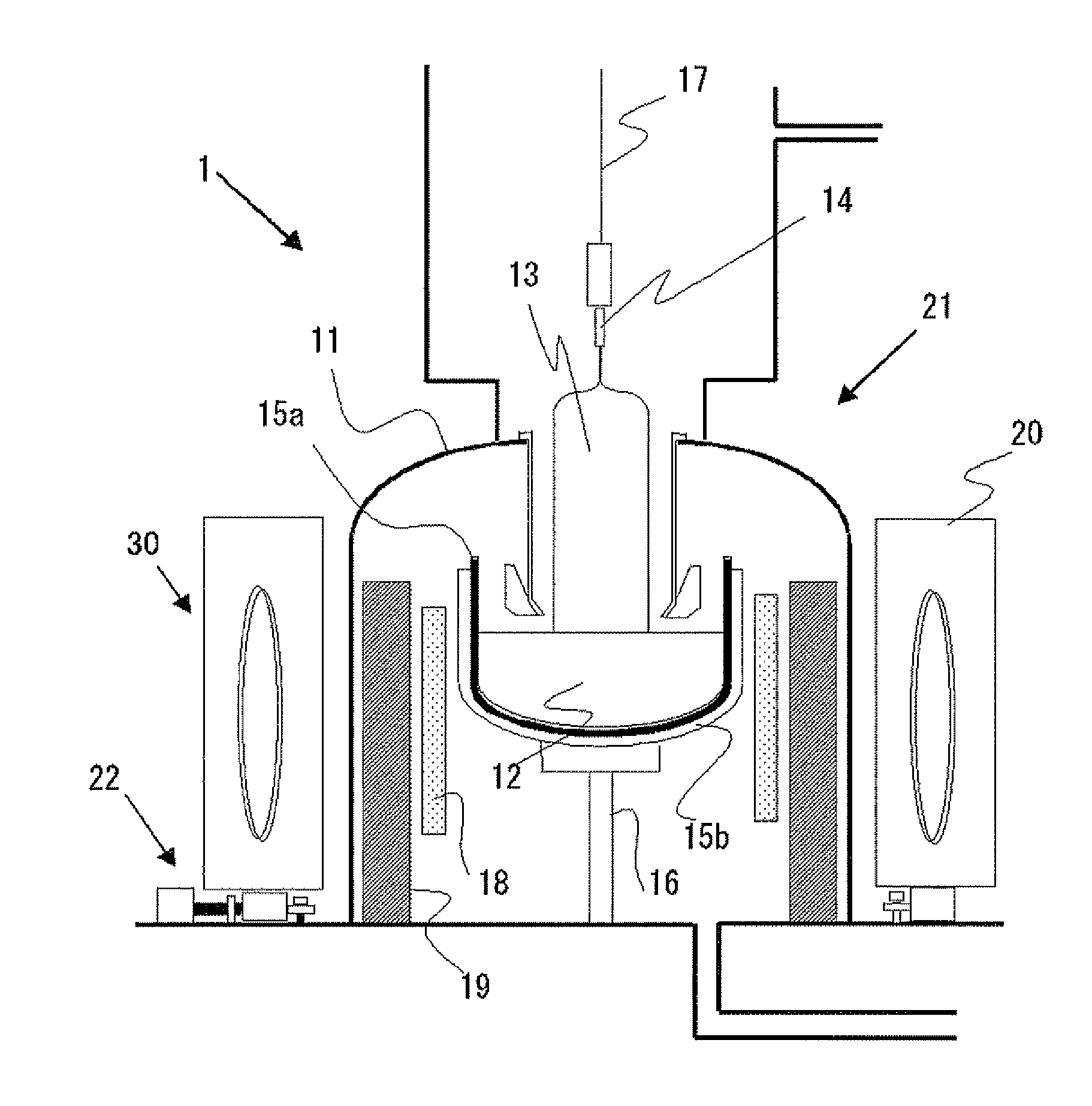
[0069]The manufacturing apparatus shown in FIG. 1 was utilized to manufacture a silicon single crystal having a diameter of 8 inches (200 mm) from a silicon melt of 200 kg. An intensity of a magnetic field generated from a magnetic field application device was set to 4000 gauss (0.4 T).

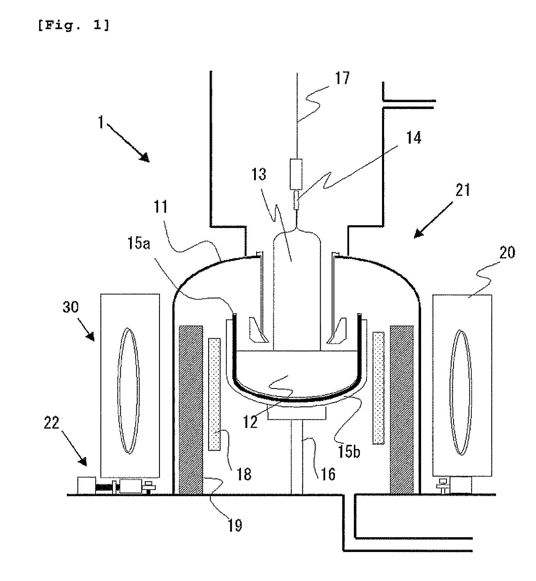
[0070]At this time, a center position of the magnetic field generated from the magnetic field application device was measured in advance as described above. Additionally, to set movement conditions for the magnetic field application device, a center position of the magnetic field on an initial stage after installation of the device was measured in advance, and the magnetic field application device was moved in the range of 2 to 14 mm to confirm a deviation position that is effective for suppression of a fluctuation in diameter and a fluctuation in oxygen concentration.

[0071]Then, the measured magnetic field center and a pulling member were deviated from a state, in which they were deviated 5 mm in an ...

example 2

[0073]The apparatus shown in FIG. 1 was utilized to manufacture a silicon single crystal having a diameter of 8 inches (200 mm) from a silicon melt of 200 kg. An intensity of a magnetic field generated from a magnetic field application device was set to 4000 gauss (0.4 T).

[0074]At this time, a center position of the magnetic field generated from the magnetic field application device was measured in advance as described above. Furthermore, the measured magnetic center and a pulling member were fixed to a state that they were deviated 5 mm in the X (left-and-right) direction before manufacture of the single crystal to manufacture the single crystal.

[0075]Further, a single crystal was manufactured in the same way as the above description except for setting the deviating direction to a Y (front-and-back) direction.


PUM

PropertyMeasurementUnit
lengthaaaaaaaaaa
lengthaaaaaaaaaa
diameteraaaaaaaaaa

Abstract

The present invention provides a silicon single crystal manufacturing method for manufacturing a single crystal based on a horizontal magnetic field applied CZ method for pulling the single crystal while applying a horizontal magnetic field to a silicon raw material melt accommodated in a quartz crucible by a magnetic field application device, comprising: measuring a center position of the magnetic field generated by the magnetic field application device; and deviating the measured center position of the magnetic field from a pulling member serving as a rotation axis of the single crystal in a horizontal direction within the range of 2 to 14 mm before manufacture of the single crystal and/or during manufacture of the single crystal. As a result, the silicon single crystal manufacturing method and manufacturing apparatus that enable manufacture of a single crystal while suppressing fluctuations in diameter and in oxygen concentration without a variation caused due to characteristics of the apparatus can be provided.

Description

TECHNICAL FIELD[0001]The present invention relates to a silicon single crystal manufacturing method based on a horizontal magnetic field applied CZ method (which will be referred to as an “HMCZ method” hereinafter) for pulling up a single crystal from a silicon raw material melt while applying a horizontal magnetic field to the silicon raw material melt in a crucible by a magnetic field application device and to a silicon single crystal manufacturing apparatus for use in this method.BACKGROUND ART[0002]A fact that the HMCZ method is superior in various points to a regular CZ method (a Czochralski method) is well known. An apparatus for use in implementation of this HMCZ method is obtained by improving an apparatus adopting the regular CZ method and has a configuration that a magnetic field application device for magnetic field application is coaxially arranged on the outside of a heater for heating a quartz crucible to face each other with the quartz crucible sandwiched therebetween...

Claims


Application Information

Patent Timeline
Patent Type & Authority Applications(United States)
IPC IPC(8): C30B15/30C30B15/00
CPCC30B15/305Y10T117/1072C30B29/06C30B35/00Y10T117/1032
Inventor MATSUMOTO, SUGURUSONOKAWA, SUSUMUUESUGI, TOSHIHARUMORI, TAKASHI
Owner SHIN-ETSU HANDOTAI CO LTD
Why Eureka
Try Eureka