
MR sensor with flux guide enhanced hard bias structure

a technology of hard bias structure and flux guide, which is applied in the field of mr sensor fabrication, can solve the problems of affecting the reading process of high density magnetic recording, less effective at orienting the free layer magnetization, and increasing the noise produced by the sensor, so as to reduce the magnetostatic coupling, promote crystalline anisotropy, and reduce the effect of coercivity

Active Publication Date: 2011-09-08
HEADWAY TECH INC
View PDF20 Cites 34 Cited by
  • Summary
  • Abstract
  • Description
  • Claims
  • Application Information

AI Technical Summary

Benefits of technology

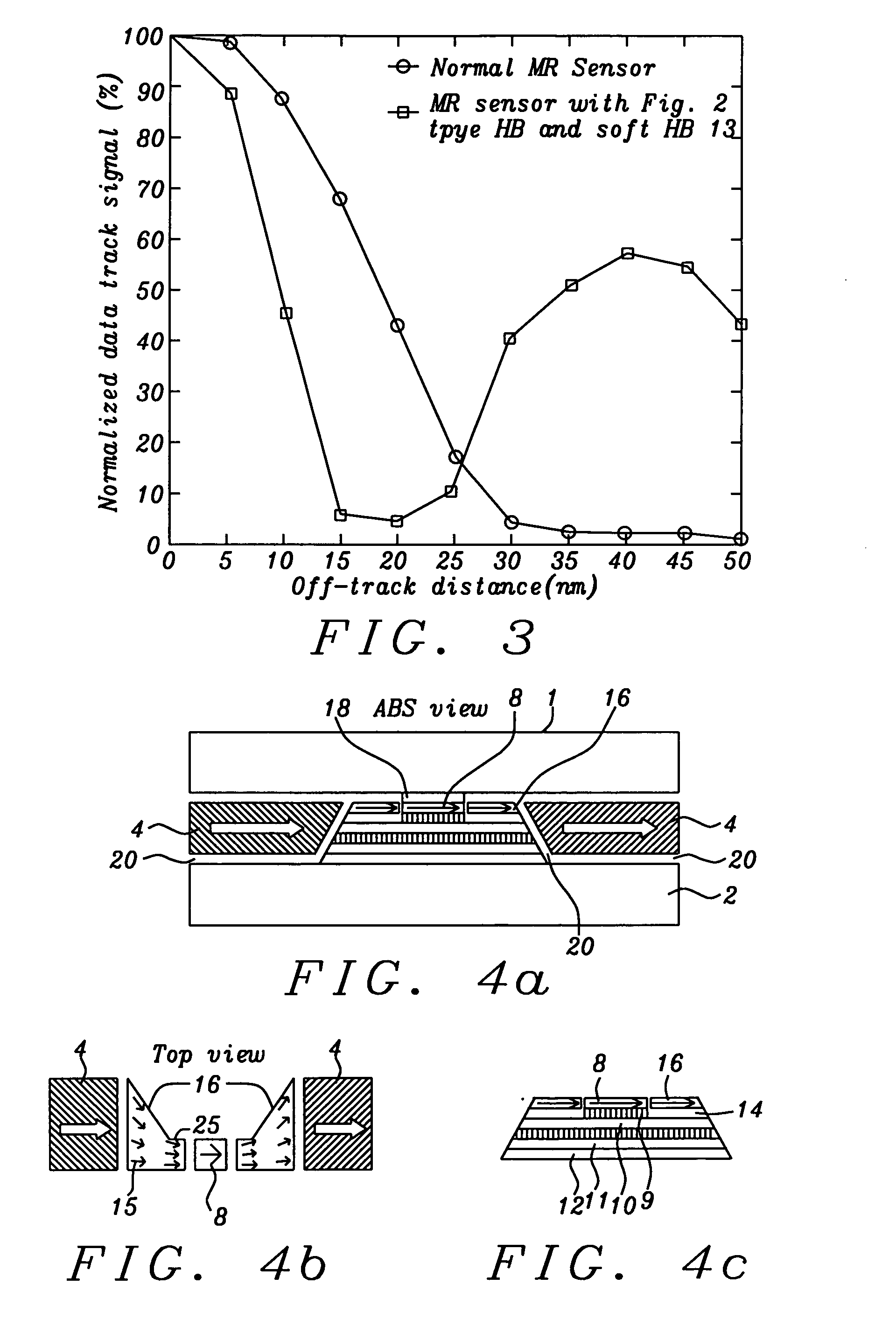
[0022]A third object of this invention is to utilize a high moment, soft magnetic flux guide structure to conduct the flux produced by a hard magnetic bias layer and to locally concentrate the flux at the free layer edges by the shape anisotropy of the flux guide and to thereby produce a high field gradient from the free layer edge to its center, i.e., to achieve an ideal HB field across the entire free layer.
[0023]A fourth object of this invention is to achieve minimal coupling between an upper (top) shield and a hard bias layer by using a flux guide structure that is a thin layer of soft magnetic material.
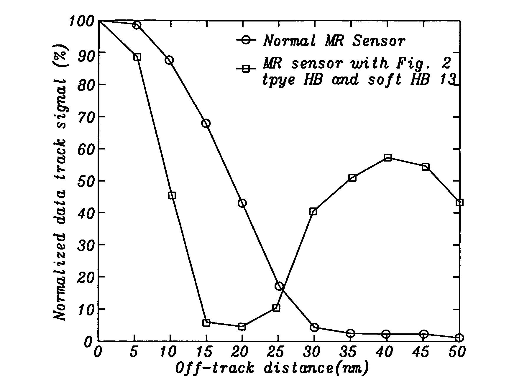
[0025]A sixth object of this invention is to attain all the previous objects while also achieving improved cross-track resolution during read-back.
[0027]The FG shall have a magnetic moment of similar or higher value than the moment of the free layer. Because of its high moment and thin layer structure, out of plane magnetization of the FG is effectively quenched by the surface demagnetization field. Thus FG magnetization will only rotate in-plane, which significantly reduces the magnetostatic interaction with the reader shield at narrow RSS.
[0032]The HB layer (4) laterally outside the FG layer is grown with the usual procedures, including the necessary underlayers (20) required to produce crystalline anisotropy, but with much less limitation on underlayer thickness than would normally be required by the imposition of a narrow RSS. The HB layer as described in this invention can be optimized for high coercivity without much impact on the actual HB field on the free layer. At the same time, the FG layer, with its tapered shape, greatly reduces the magnetostatic coupling between the FG and the free layer through back-end magnetic charges. As a result, side reading due to FG coupling to the free layer is eliminated.

Problems solved by technology

The fewer the magnetic charges, the less is the pinning field of the HB layers and the less effective they are at orienting the free layer magnetization.
Studies (see: Y. Zhou, “Thermally Excited Low Frequency Magnetic Noise in CPP Structure MR Heads,” IEEE Trans. Magn., vol 43, pp 2187, 2007) show that a weakened HB field increases the noise produced by the sensor and will ultimately affect the reading process in high density magnetic recording.
However, increasing the magnetic moment and increasing the coercivity of the HB materials are contradictory procedures according to the physics of magnetic materials.
Thus, a high moment, high coercivity HB material is difficult to achieve so that it produces enough HB field on the free layer and is stable enough at narrow RSS.
According to the prior study of Y. Zhou, cited above, this limitation on the minimum HB-to-sensor stack distance leads to a lower HB field gradient from the free layer edge to the free layer center.

Method used


Image

  • MR sensor with flux guide enhanced hard bias structure
  • MR sensor with flux guide enhanced hard bias structure
  • MR sensor with flux guide enhanced hard bias structure

Examples


embodiment 1

[0051]In what follows, for ease and consistency of description, laterally directed dimensions (in the ABS plane) will be denoted “widths,” vertically directed dimensions (in the ABS plane) will be denoted “thicknesses” and dimensions directed from the ABS plane of the sensor towards the backside will be denoted “depths.” If other terms are utilized, they will be defined as needed. For example, the depth direction will sometimes be referred to as the “stack height.”

[0052]Referring now to schematic FIGS. 4a, 4b and 4c, there is shown, first, in FIG. 4a, an ABS view of a first embodiment of the present invention. Reader shields (1) (top or upper shield) and (2) (bottom shield) are formed above and below the CPP MR sensor stack (6) that is patterned to accept the short substantially vertical edges of the flux guides (16) on either side of the substantially vertical edges free layer (8). The sensor stack is a vertical lamination of horizontal layers that will be described below. The read...

embodiment 2

[0067]Referring now to schematic FIGS. 8a, 8b and 8c, there is shown, first, in FIG. 8a, an ABS view of a second embodiment of the present invention, in FIG. 8b there is shown a top view (cross-section between the shields) of FIG. 8a and in FIG. 8c there is shown a more detailed view of the sensor stack (6) components and the positioning of the FG layer (16) and its magnetization vectors (arrows).

[0068]Reader shields (1) (top or upper shield) and (2) (bottom shield) are formed above and below (RSS separation approximately 10 to 40 nm) the CPP MR sensor stack (6) that is patterned to accept the short edges of the flux guides (FG) (16) on the etched slopes of the sensor stack. These etched slopes can extend through more than two layers of the MR stack. It is noted that the width of the free layer (8) is between approximately 10 and 100 nm and the widths of the layers (9)-(12) below the free layer are greater, corresponding to the slope of the sides. Unlike the patterned shape of FIG. ...


PUM


Abstract

A CPP MR sensor interposes a tapered soft magnetic flux guide (FG) layer between a hard magnetic biasing layer (HB) and the free layer of the sensor stack. The flux guide channels the flux of the hard magnetic biasing layer to effectively bias the free layer, while eliminating instability problems associated with magnetostatic coupling between the hard bias layers and the upper and lower shields surrounding the sensor when the reader-shield-spacing (RSS) is small.

Description

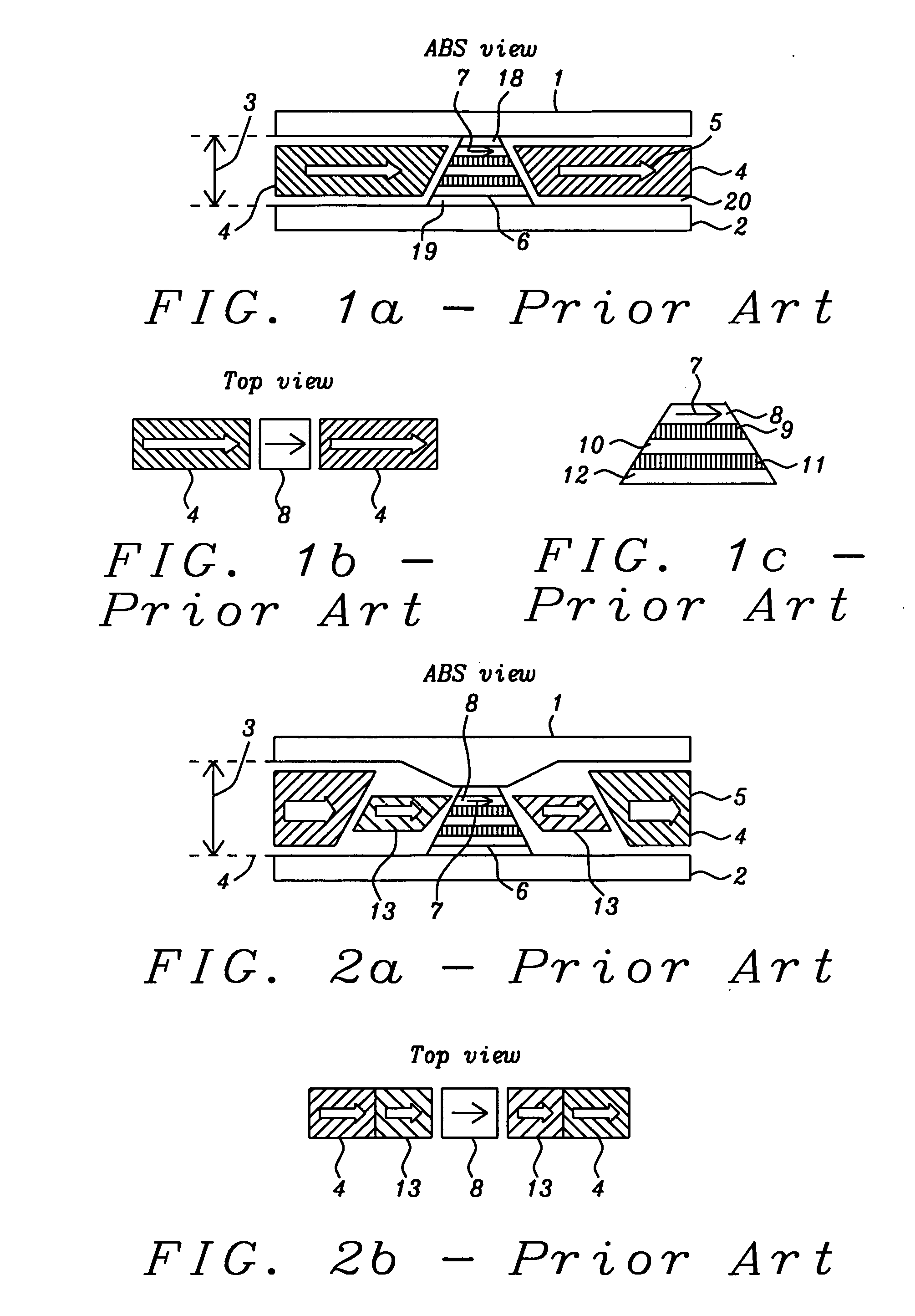
BACKGROUND OF THE INVENTION[0001]1. Field of the Invention[0002]This invention relates generally to the fabrication of a MR sensor. In particular it relates to an MR sensor in which a hard bias layer can be reduced in thickness and enhanced in effect by means of a flux guide structure.[0003]2. Description of the Related Art[0004]With the ever increasing areal density with which data is stored on magnetic media such as disks in hard disk drives (HDD), the magneto-resistive (MR) sensor that is used as the read-back element in the HDD is required to have a correspondingly improved spatial resolution while achieving and maintaining a reasonable signal-to-noise ratio (SNR). Referring to schematic FIGS. 1a, 1b and 1c, there are shown three views of a generic, prior-art current-perpendicular-to-plane (CPP) MR read head. FIG. 1a illustrates the read head in a vertical cross-sectional plane parallel to its air bearing surface (ABS) plane. FIG. 1b illustrates the read head from an overhead vi...

Claims


Application Information

Patent Timeline
Patent Type & Authority Applications(United States)
IPC IPC(8): G01R33/02B44C1/22
CPCB82Y25/00G01R33/0011G11B5/398G11B5/3932G11B5/3941G01R33/093
Inventor ZHOU, YUCHENZHAO, TONGZHANG, KUNLIANG
Owner HEADWAY TECH INC
Learn More