Mask frame assembly for thin film deposition and method of assembling the same

a technology of mask frame and thin film, which is applied in the direction of vacuum evaporation coating, manufacturing tools, coatings, etc., can solve the problems of etching error occurring when the pattern is formed, affecting the etching efficiency of the mask frame, so as to achieve the effect of improving the structure and preventing the deformation of the mask fram

Active Publication Date: 2011-09-15
SAMSUNG DISPLAY CO LTD
View PDF3 Cites 82 Cited by
  • Summary
  • Abstract
  • Description
  • Claims
  • Application Information

AI Technical Summary

Benefits of technology

[0012]The present invention provides a mask frame assembly for thin film deposition, having an improved structure in which deformation of a frame can be stably prevented after assembling of a mask and the frame is completed, and a method of assembling the same.
[0015]A shielding mask may be attached to the balance stick to shield a gap between the balance stick and the masks.

Problems solved by technology

However, it may be difficult to achieve high light-emission efficiency with such a structure, and thus intermediate layers, including an electron injection layer, an electron transport layer, a hole transport layer, a hole injection layer, etc., are optionally located between the emission layer and each of the electrodes.
As the size of the FMM increases, the possibility of an etching error occurring when the pattern is formed increases, and often, a middle portion of the FMM sags due to its weight.
Although sagging of the divided mask occurs relatively infrequently compared to an undivided large-sized mask, sagging may still occur in the divided mask.
However, when the divided mask is welded to the frame while being extended in the manner described above, the frame may be deformed due to an elastic biasing force from the divided mask.
This means that the probability of accurately calculating the counter force when all of the divided masks have the same tensile characteristics is high, but in reality, characteristics of the divided masks are different from one another and thus the probability of accurately calculating the counter force is not perfect.
As a result, the precise patterns that should be formed by a deposition process may be distorted.

Method used


Image

  • Mask frame assembly for thin film deposition and method of assembling the same
  • Mask frame assembly for thin film deposition and method of assembling the same
  • Mask frame assembly for thin film deposition and method of assembling the same

Examples


Embodiment Construction

[0024]Embodiments of the present invention will now be described more fully with reference to the accompanying drawings.

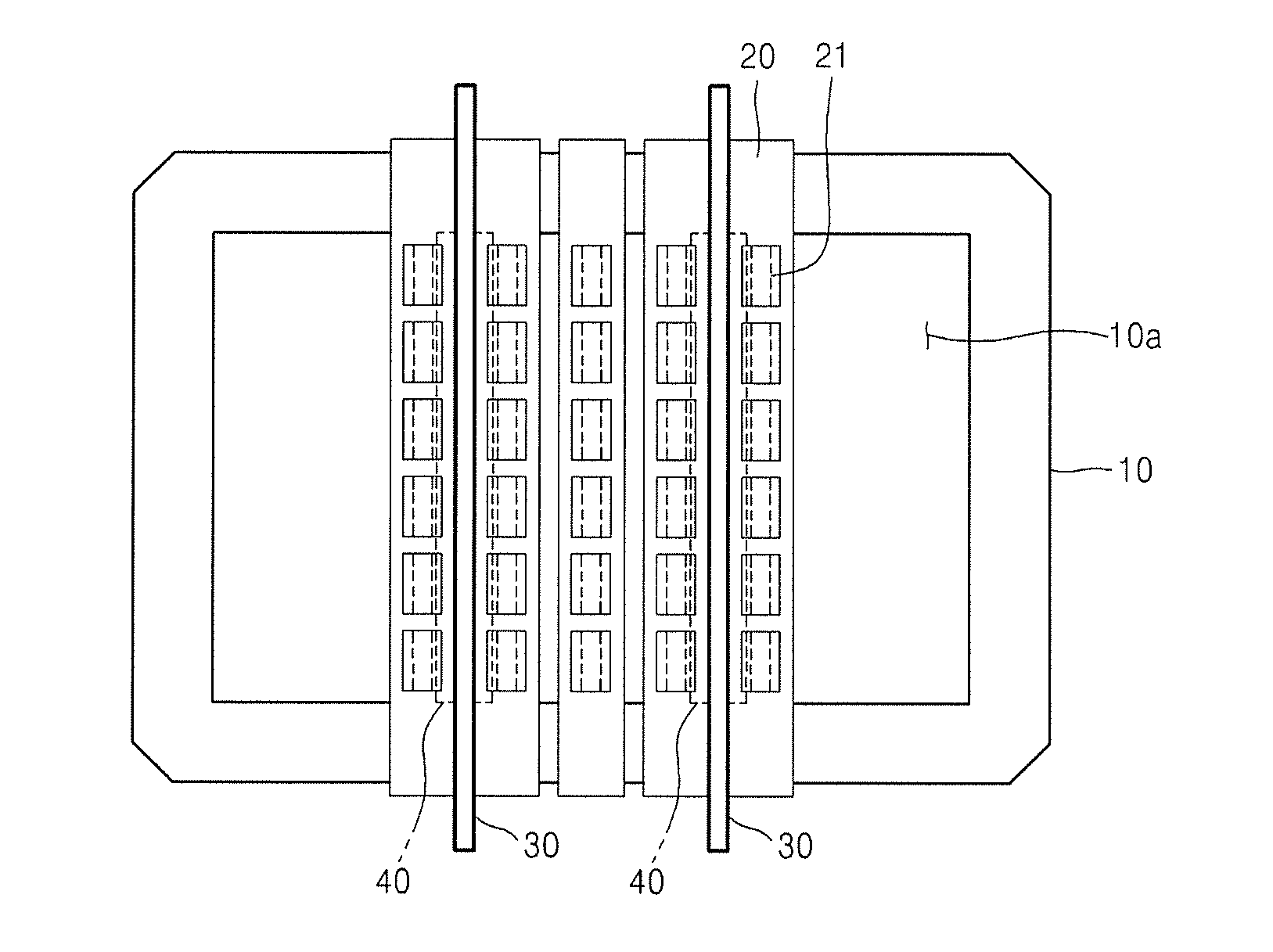
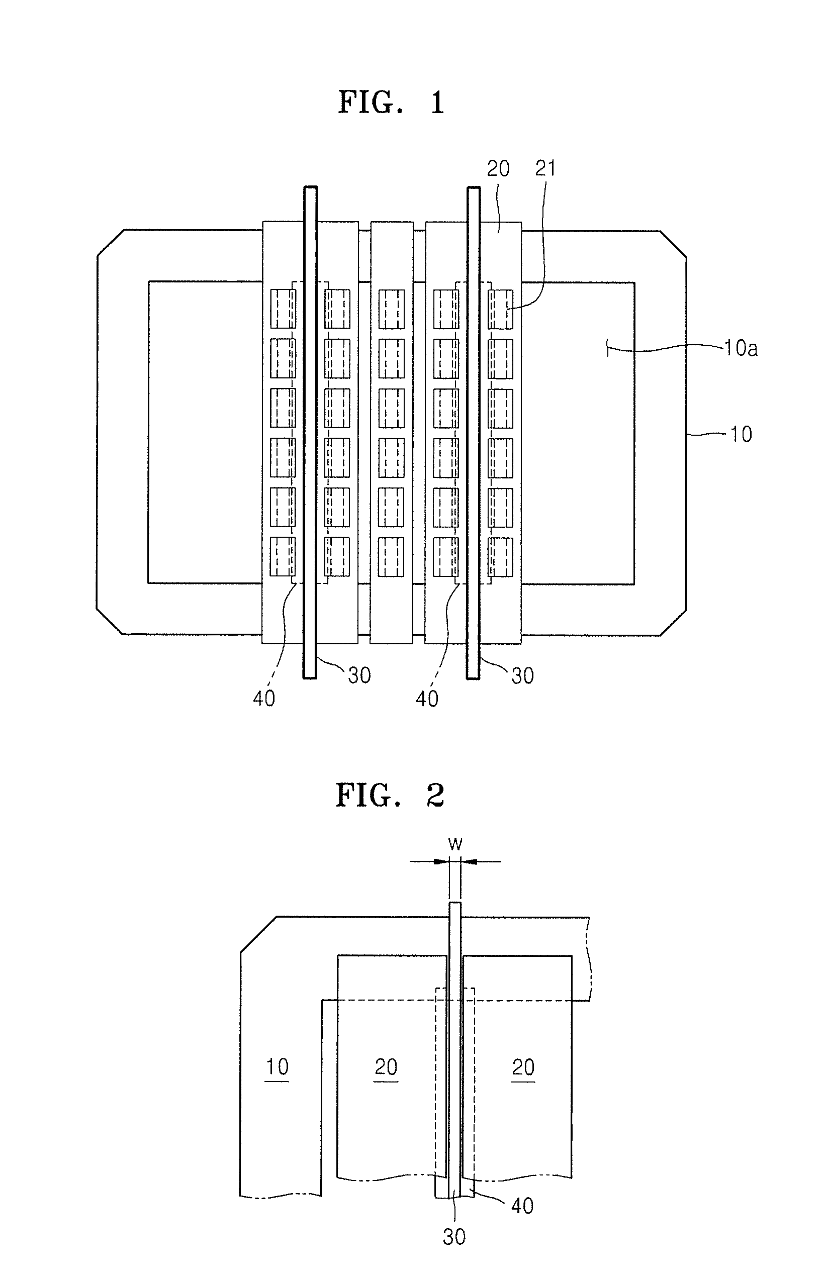
[0025]FIG. 1 is a plan view of a mask frame assembly for thin film deposition, according to an embodiment of the present invention. Referring to FIG. 1, the mask frame assembly includes a frame 10 having an opening 10a, a plurality of masks 20 having end portions fixed to the frame 10, and a balance stick 30. In FIG. 1, for convenience of explanation, only five masks 20 are shown so as to show the opening 10a. However, in one embodiment, after assembling of the masks 20 is completed, the opening 10a is fully covered by the masks 20 (see FIG. 4H).

[0026]The frame 10 forms an outer frame of the mask frame assembly and has a substantially rectangular shape in which the opening 10a is formed in the middle of the frame 10. The end portions of the masks 20 and end portions of the balance stick 30 are fixed to a pair of opposite sides of the frame 10 by a welding process.

[...


PUM

PropertyMeasurementUnit
thicknessaaaaaaaaaa
thicknessaaaaaaaaaa
elastically tensileaaaaaaaaaa

Abstract

A mask frame assembly for thin film deposition, the mask frame assembly including a frame having an opening; a plurality of masks having deposition patterns, the masks being fixed to the frame such that the deposition patterns extend over the opening; and a balance stick being fixed to the frame such that the balance stick is between two of the plurality of masks, the balance stick made from an elastically tensile material.

Description

CROSS-REFERENCE TO RELATED APPLICATION[0001]This application claims priority to Korean Patent Application No. 10-2010-0021010, filed on Mar. 9, 2010, in the Korean Intellectual Property Office, the entire disclosure of which is incorporated herein by reference.BACKGROUND[0002]1. Field[0003]The present invention relates to a mask frame assembly for thin film deposition.[0004]2. Description of Related Art[0005]Generally, organic light emitting display devices have superior characteristics such as wide viewing angles, high contrast ratios, and short response times.[0006]Organic light-emitting display devices generally have a stacked structure including an anode, a cathode, and an emission layer located between the anode and the cathode. The devices display color images when holes and electrons, injected respectively from the anode and the cathode, recombine in the emission layer, which causes an emission of light. However, it may be difficult to achieve high light-emission efficiency w...

Claims


Application Information

Patent Timeline
Patent Type & Authority Applications(United States)
IPC IPC(8): B05C11/00B23P11/00
CPCY10T29/49826C23C14/042H01L51/0011H01L51/56H10K71/166H10K71/00C23C16/042
Inventor LEE, CHOONG-HOOH, YOON-CHANLEE
Owner SAMSUNG DISPLAY CO LTD
Why Eureka
Try Eureka