Gas transfer device and use of a structured membrane
- Summary
- Abstract
- Description
- Claims
- Application Information
AI Technical Summary
Benefits of technology
Problems solved by technology
Method used
Image

Examples
Embodiment Construction
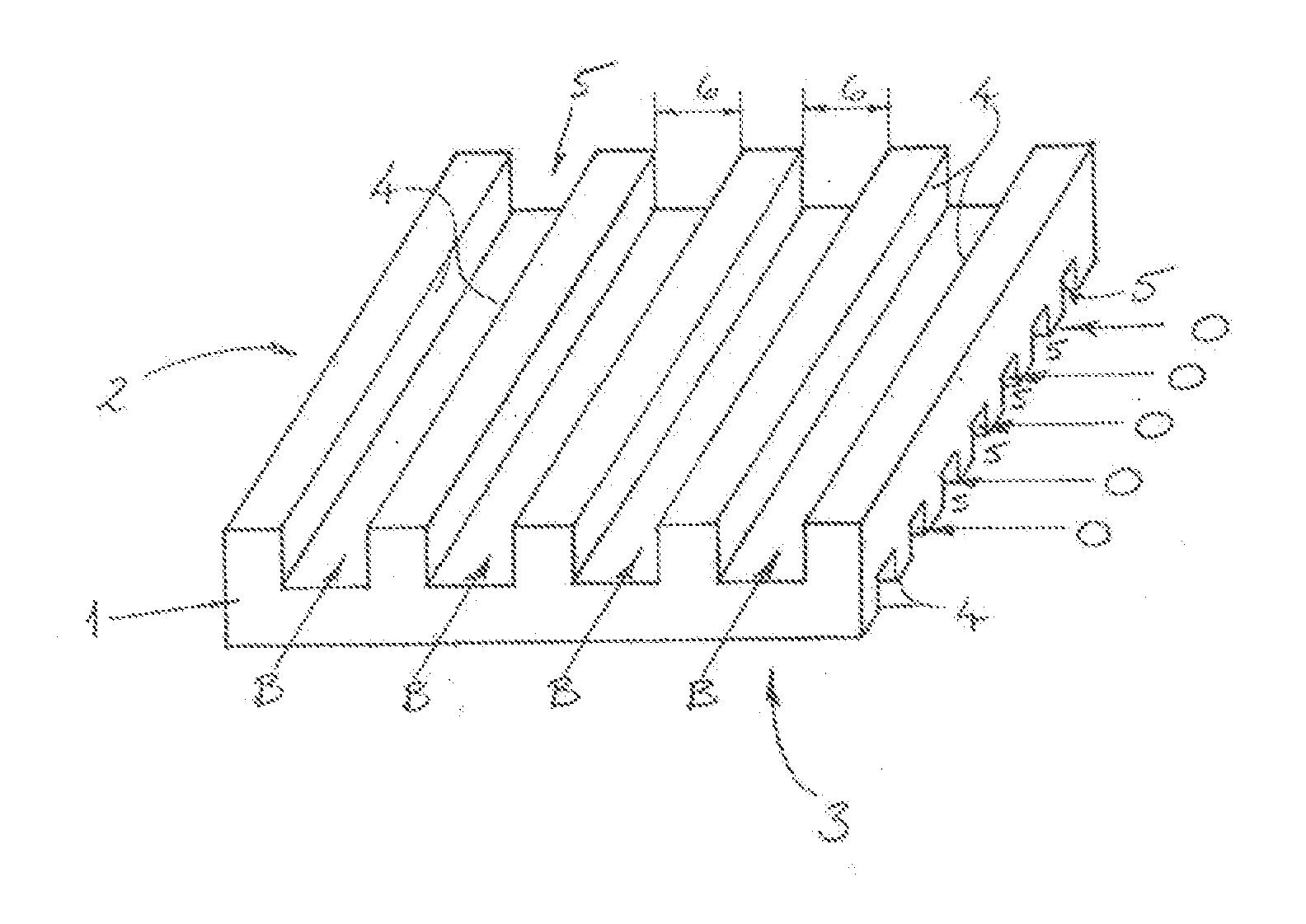
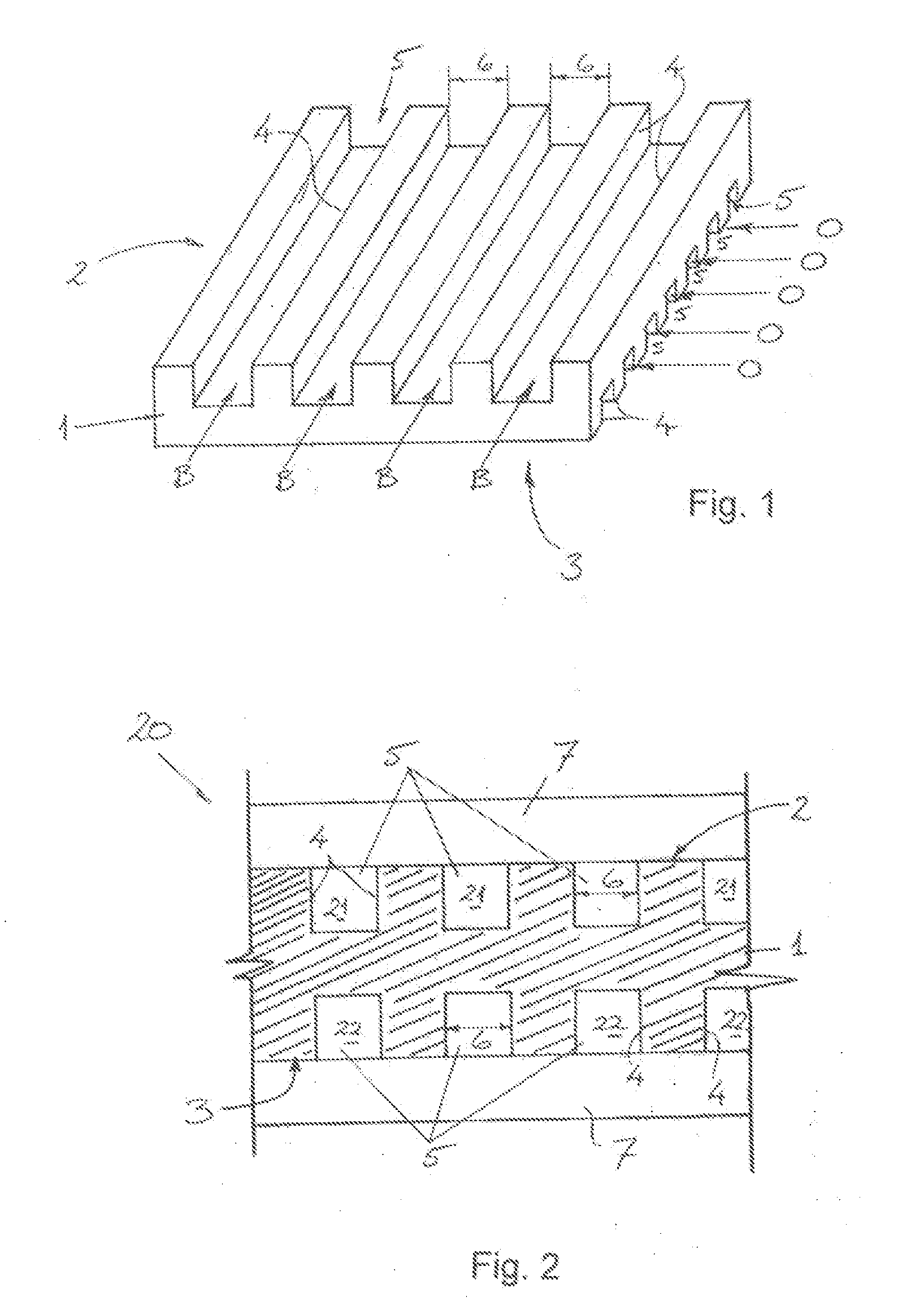
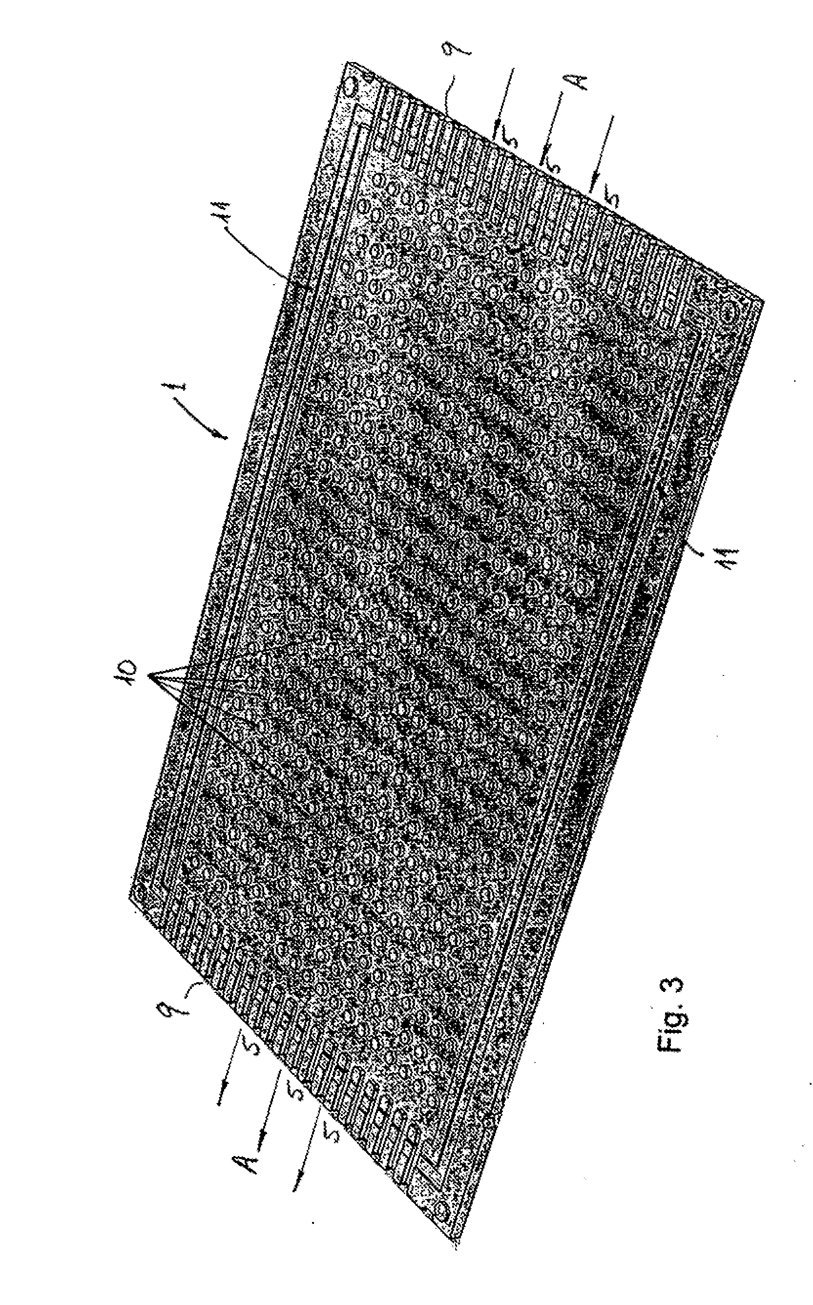
[0011]The object of the present invention is accordingly to provide improved gas transfer devices which may be used in chemistry, biotechnology and medicine, in particular for gassing or for gas exchange in the blood. In particular, the following invention is intended to provide a gas transfer device having improved gas transfer through the membrane and having an increased useful life.
[0012]This object is achieved according to the invention by the gas transfer device stated according to the main claim, which comprises at least two chambers and at least one gas-permeable and liquid-impermeable membrane, the chambers being separated from one another by the membrane(s), and which are characterised in that the membrane(s) is / are structured on at least one side and channels and / or branching structures are formed on the membrane by said structuring or structure, the walls of which have a spacing of ≦500 μm, preferably of ≦250 μm, and more preferably of ≦150 μm, and the proportion of the m...
PUM
| Property | Measurement | Unit |
|---|---|---|
| Length | aaaaa | aaaaa |
| Length | aaaaa | aaaaa |
| Length | aaaaa | aaaaa |
Abstract
Description
Claims
Application Information
 - R&D Engineer
- R&D Manager
- IP Professional
- Industry Leading Data Capabilities
- Powerful AI technology
- Patent DNA Extraction
Browse by: Latest US Patents, China's latest patents, Technical Efficacy Thesaurus, Application Domain, Technology Topic.
© 2024 PatSnap. All rights reserved.Legal|Privacy policy|Modern Slavery Act Transparency Statement|Sitemap