Ultraviolet light irradiation device

a technology of ultraviolet light and irradiation device, which is applied in the direction of energy-saving lighting, sustainable buildings, and therapy, etc., can solve the problems of inability to easily increase the size of the device, complicated configuration, and inability to adapt to the needs of us

Inactive Publication Date: 2011-09-22
SHINODA PLASMA +1
View PDF10 Cites 8 Cited by
  • Summary
  • Abstract
  • Description
  • Claims
  • Application Information

AI Technical Summary

Benefits of technology

[0031]In the tenth invention, it is easy to visually confirm where the UV light is irradiated.
[0032]In the present invention, the irradiation intensity of ultraviolet light can be adjusted in a wider range as compared to the case where, for example, an extra high pressure mercury lamp or an ultraviolet fluorescent lamp is used for the ultraviolet light source. Furthermore, a selection of an electrode pair to which a pulse voltage is applied makes it possible to adjust the range where ultraviolet light can be irradiated.

Problems solved by technology

However, ultraviolet light irradiation devices in which extra high pressure mercury lamps, which are point light sources, or ultraviolet fluorescent lumps, which are line light sources, are used for UV light sources have a problem in that an optically complicated configuration is necessary in order to obtain ultraviolet light with uniform irradiation intensity in the range where ultraviolet light can be irradiated.
However, the flat-type ultraviolet fluorescent lamp has a technical difficulty to form a large discharge chamber and therefore cannot be increased in size easily.
Moreover, since the flat-type ultraviolet fluorescent lamp is configured with two glass substrates disposed to be opposed to each other, it has no is flexibility and therefore cannot configure a curved emitting surface of the UV light source.
Furthermore, the extra high pressure mercury lamps or the ultraviolet fluorescent lamps have a problem in that the irradiation intensity of UV light cannot be adjusted finely in a wide range.

Method used


Image

  • Ultraviolet light irradiation device
  • Ultraviolet light irradiation device
  • Ultraviolet light irradiation device

Examples


embodiment 1

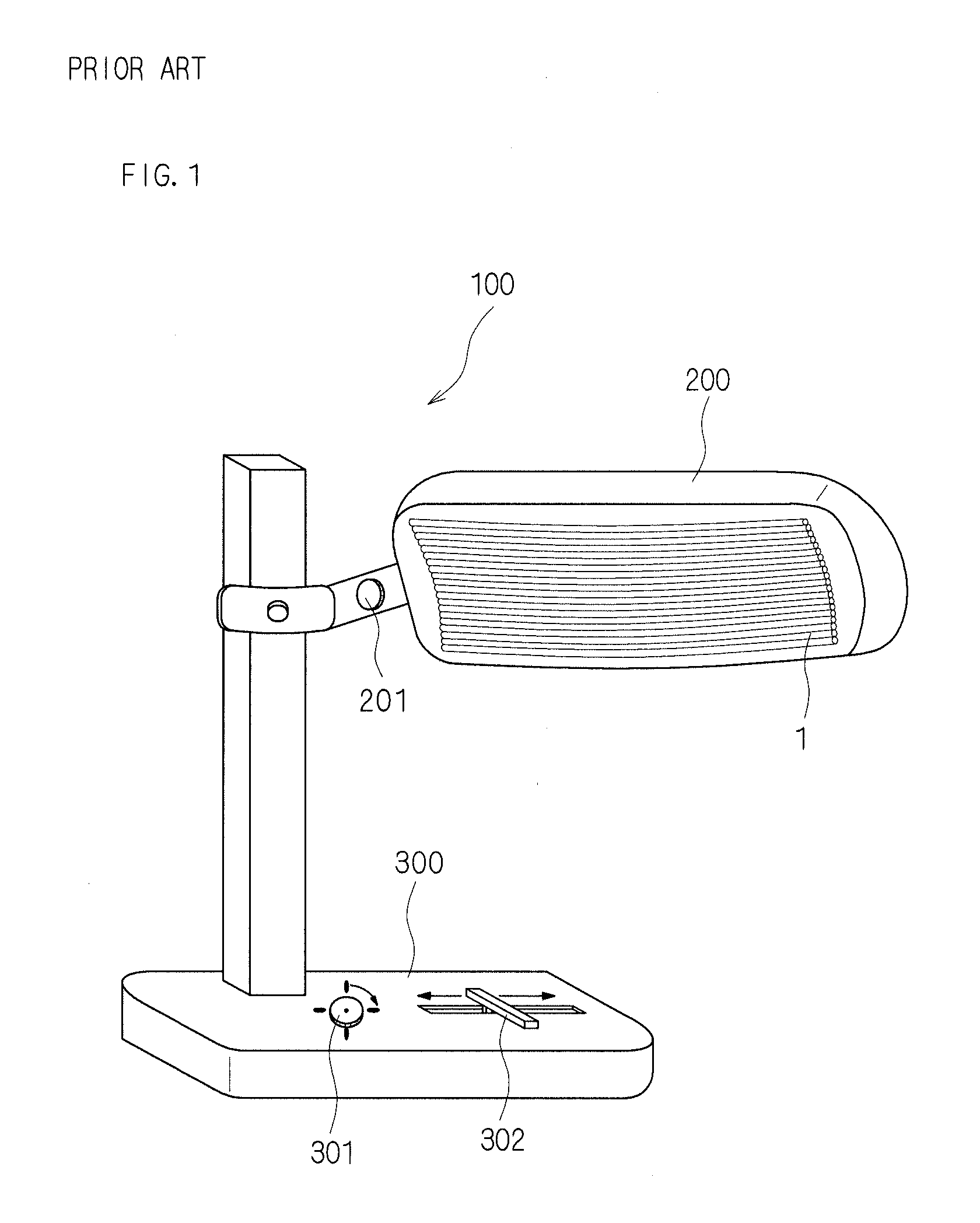
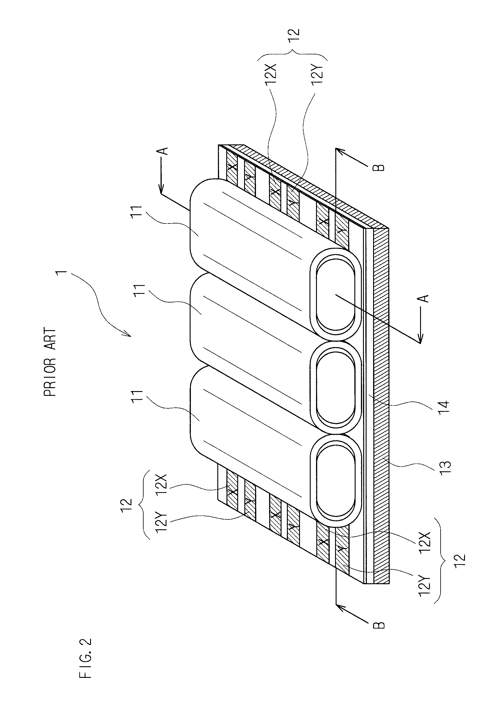
[0047]Hereinafter, an ultraviolet light irradiation device according to Embodiment 1 of the present invention is described in detail with reference to the drawings. FIG. 1 is a schematic view showing the appearance of the ultraviolet light irradiation device according to Embodiment 1 of the present invention. The ultraviolet light irradiation device 100 shown in FIG. 1 comprises an ultraviolet light source 1, a housing 200 that functions as a backboard for holding the ultraviolet light source 1 and accommodates a drive circuit, and a support stand 300 that supports the housing 200 and also serves as a control box. The ultraviolet light irradiation device 100 is an ultraviolet light irradiation device for medical use and is a therapy apparatus for irradiating ultraviolet light with a wavelength of UV-B band that is effective for a medical treatment of, for example, psoriasis, atopic dermatitis, or vitiligo. In the ultraviolet light irradiation device 100, the angle of irradiation of ...

embodiment 2

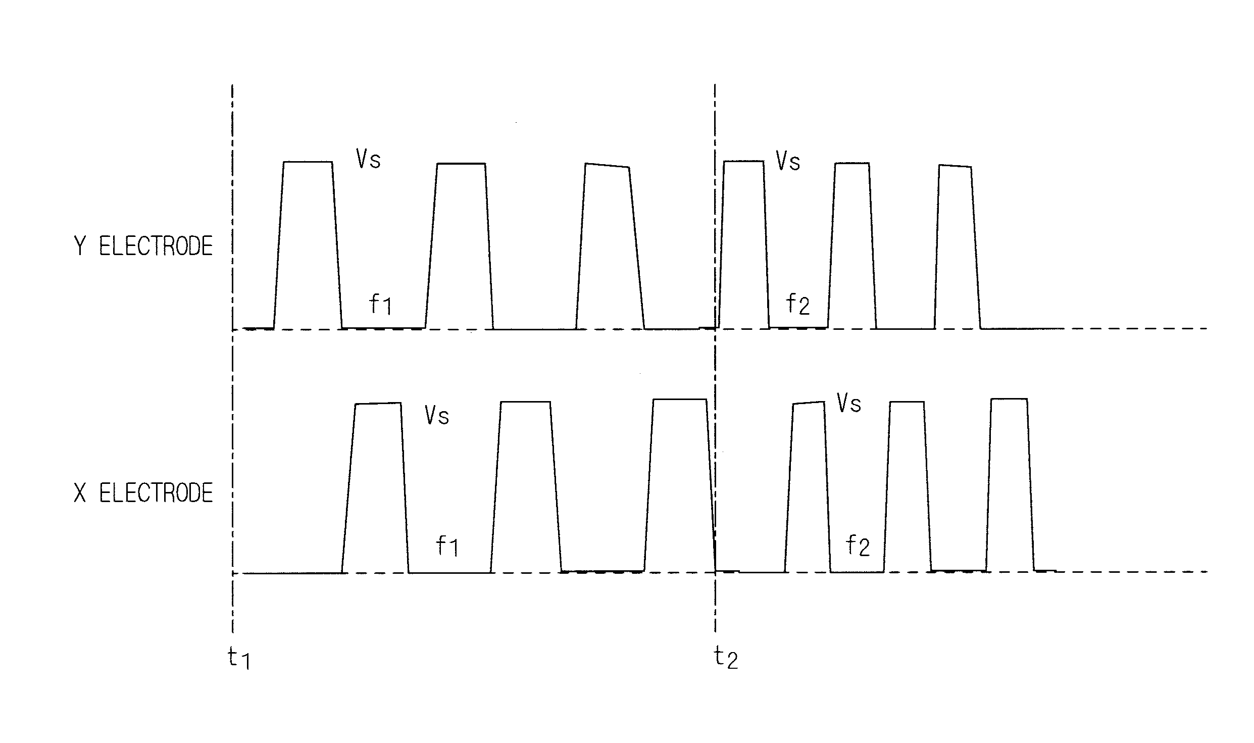
[0065]An ultraviolet light irradiation device 100 according to Embodiment 2 of the present invention is identical to that according to Embodiment 1 except that the circuit configuration of the ultraviolet light source 1 is different in having a function of adjusting the range where ultraviolet light can be irradiated. Therefore, the detailed description thereof is not repeated. FIG. 12 is a circuit diagram showing the basic configuration of a circuit for selectively driving and lighting the ultraviolet light source 1 according to Embodiment 2 of the present invention. As shown in FIG. 12, the electrode pairs 12, 12, . . . are provided in the direction substantially orthogonal to the longitudinal direction of the thin plasma tubes 11, 11, . . . and the X electrodes 12X, 12X, . . . are divided to be connected to a plurality of the electrode connectors 61X, 61X, and 61X, respectively, according to the configuration of the connectors, but the Y electrodes 12Y, 12Y, . . . are divided to ...


PUM


Abstract

The present invention provides an ultraviolet light irradiation device having a planer UV light source in which the irradiation intensity of UV light can be adjusted finely in a wider range. The ultraviolet light irradiation device of the present invention comprises an UV light source and a housing that holds the planer UV light source. In the UV light source, a plurality of thin plasma tubes, each of which has an UV phosphor layer formed therein, are arranged in parallel with each other on an electrode support sheet, and drive circuits apply a pulse voltage to electrode pairs provided between the electrode support sheet and an array of the thin plasma tubes. A control circuit controls a factor of the pulse voltage to be applied to the electrode pairs so as to adjust the irradiation intensity of the UV light.

Description

[0001]This application claims the priority benefit of Japanese Application No. 2010-061453, filed Mar. 17, 2010, the disclosure of which is incorporated in its entirety by reference.BACKGROUND OF THE INVENTION[0002]1. Field of the Invention[0003]The present invention relates to an ultraviolet light irradiation device having a planar UV (ultraviolet) light source, particularly, an ultraviolet light irradiation device with an array of a plurality of thin plasma tubes arranged in parallel with each other as the UV light source.[0004]2. Description of the Related Art[0005]Conventionally, for example, extra high pressure mercury lamps and ultraviolet fluorescent lamps are employed widely as UV light sources used for ultraviolet light irradiation devices. Particularly, extra high pressure mercury lamps are often used as the UV light sources for semiconductor exposure apparatuses that require high irradiation intensity of ultraviolet light.[0006]On the other hand, in the field of the ultra...

Claims


Application Information

Patent Timeline
Patent Type & Authority Applications(United States)
IPC IPC(8): H05B41/16
CPCH01J65/046Y02B20/22H05B41/2806Y02B20/00A61N5/06A61N5/00
Inventor AWAMOTO, KENJIGUO, BINGANGSHINOHE, KOJISHINODA, TSUTAECHIGI, YOSHITAKANISHIMOTO, TETSUROTANAKA, HIROYUKIKOBAYASHI, MIKIHIRO
Owner SHINODA PLASMA
Why Eureka
Try Eureka