Method for determining the suction mass flow of a gas turbine

a gas turbine and mass flow technology, applied in the direction of gas turbine engine testing, machines/engines, instruments, etc., can solve the problems of comparatively difficult to determine values and high degree of error, and achieve accurate analysis of the degree of contamination, low statistical error, and high efficiency of gas turbines

Inactive Publication Date: 2011-10-13
SIEMENS AG
View PDF14 Cites 14 Cited by
  • Summary
  • Abstract
  • Description
  • Claims
  • Application Information

AI Technical Summary

Benefits of technology

[0031]This allows balancing between the data of structurally identical and / or structurally similar gas turbines, with the result that backup by an especially broad experimental base can occur and therefore a lower statistical error is achieved. Conversely, the data obtained in the gas turbine may also be used for extending the database, in that they are made available to the database and stored there.
[0032]Advantageously, a prediction module for use in a gas turbine plant is suitable for carrying out the method. The advantages achieved by means of the invention are, in particular, that, by determining the suction mass flow of the gas turbine by means of the turbine inlet pressure, the combustion chamber pressure loss and / or the pressure loss between the surroundings and the compressor inlet, a comparatively accurate analysis of the degree of contamination of the gas turbine, in particular of its compressor, is possible. It is thereby possible to carry out a predictive planning, adapted to the operational and economic circumstances, of the offline scrubbing of the gas turbine, with the result that an especially high efficiency of the gas turbine can be achieved during its running time. Moreover, the method described here makes it possible to determine the suction mass flow without any knowledge of the fuel data and without solving an energy balance associated with high uncertainties. Furthermore, it is consequently possible for the first time to take into account the suction mass flow in respect of the operating power of the gas turbine for single-shaft plants in which a gas turbine and a steam turbine are arranged on a common shaft.

Problems solved by technology

However, these values are comparatively difficult to determine and have a very high degree of error.

Method used


Image

  • Method for determining the suction mass flow of a gas turbine
  • Method for determining the suction mass flow of a gas turbine
  • Method for determining the suction mass flow of a gas turbine

Examples


Embodiment Construction

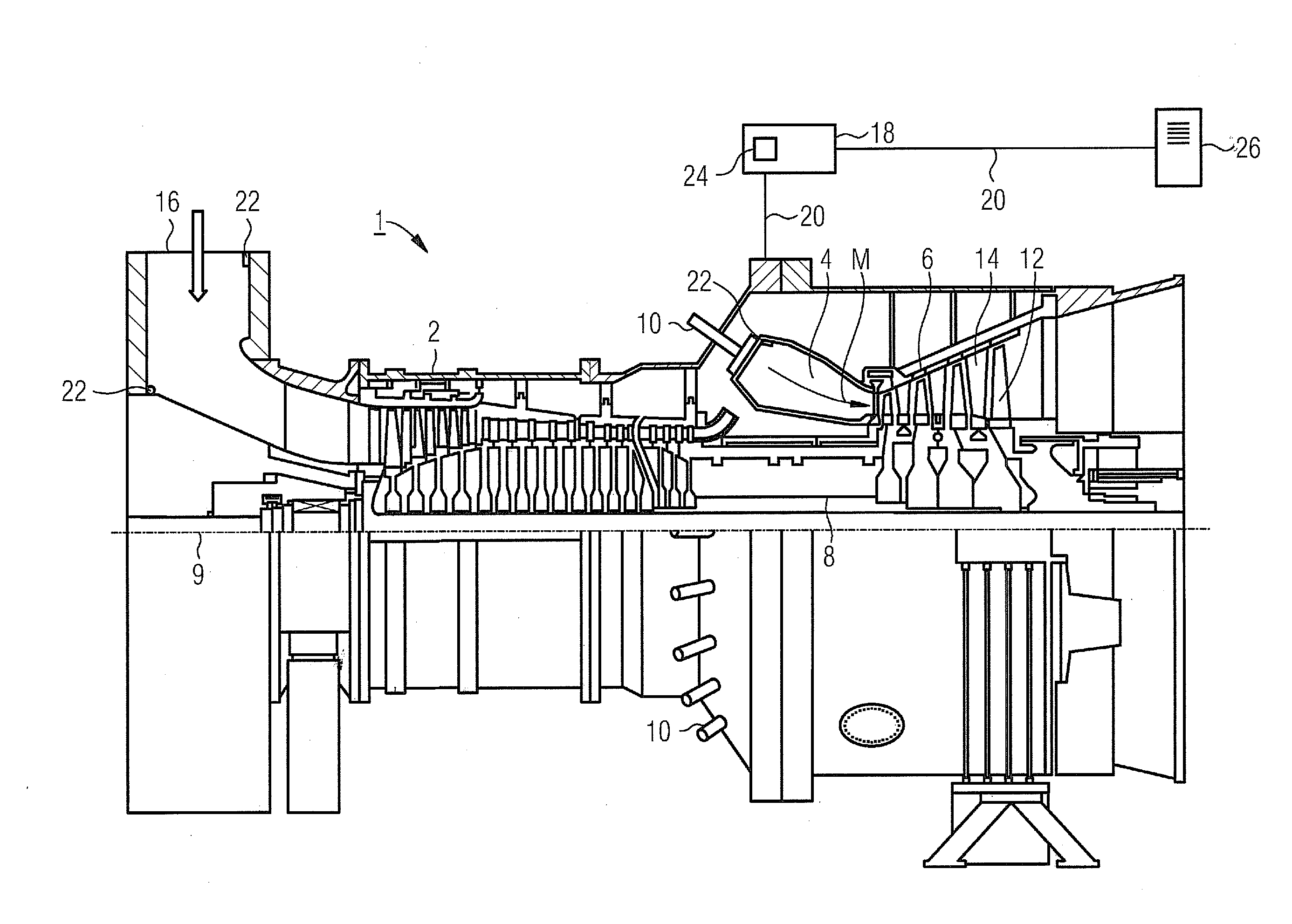
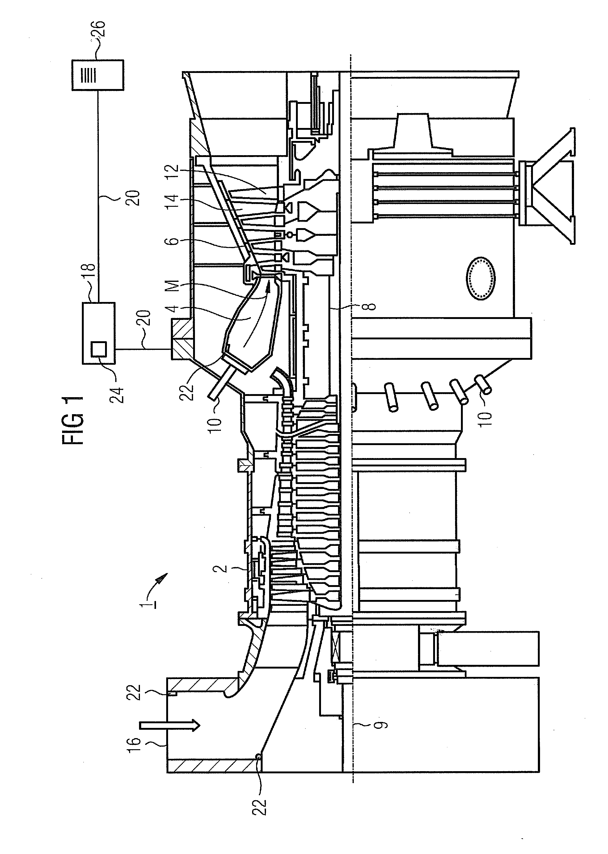
[0038]The gas turbine 1 according to FIG. 1 has a compressor 2 for combustion air, a combustion chamber 4 and a turbine 6 for the drive of the compressor 2 and of a generator or a working machine, not illustrated in any more detail. For this purpose, the turbine 6 and compressor 2 are arranged on a common turbine shaft 8, also designated as a turbine rotor, to which the generator or the working machine is also connected and which is mounted rotatably about its mid-axis 9.

[0039]The combustion chamber arrangement 4 comprises a number of individual burners 10, arranged around the turbine shaft 8 in the form of a ring, for the combustion of a liquid or gaseous fuel.

[0040]The turbine 6 has a number of rotatable moving blades 12 connected to the turbine shaft 8. The moving blades 12 are arranged in the form of a ring on the turbine shaft 8 and thus form a number of moving blade rows. Furthermore, the turbine 6 comprises a number of stationary guide vanes 14 which are likewise fastened in ...


PUM


Abstract

A method for determining a suction mass flow of a gas turbine is provided. A turbine inlet pressure, a combustion chamber pressure loss and a pressure loss between an environment and a compressor inlet are determined as input parameters. For each input parameter a provisional value for the suction mass flow is ascertained and for each provisional value a validated value by cross-balancing with the other provisional values is ascertained. A characteristic quantity of the suction mass flow of the gas turbine is generated as an average value from the validated values. The suction mass flow is determined without solving energy balances, without information relating to a fuel calorific value, and without information relating to a fuel mass flow.

Description

CROSS REFERENCE TO RELATED APPLICATIONS[0001]This application is the US National Stage of International Application No. PCT / EP2009 / 053440 filed Mar. 24, 2009, and claims the benefit thereof. The International Application claims the benefits of European Application No. 08005950.4 EP filed Mar. 28, 2008. All of the applications are incorporated by reference herein in their entirety.FIELD OF INVENTION[0002]The invention relates to a method for determining the suction mass flow of a gas turbine. It relates, further, to a method for diagnosing a gas turbine comprising a plurality of components, in which the additional power, by the amount of which the operating power of the gas turbine would be increased in the event of a cleaning of one of the components, is automatically predicted.BACKGROUND OF INVENTION[0003]In a gas turbine, during the running time, its power and efficiency decrease due to contamination, deposits, erosion and corrosion, with the result that the overall power station ...

Claims


Application Information

Patent Timeline
Patent Type & Authority Applications(United States)
IPC IPC(8): G01M15/14
CPCF01D25/002F05D2270/71F05D2270/708F05D2270/44G07C3/00
Inventor GROSSE-LAXZEN, ROLFWERNER, KLAUS
Owner SIEMENS AG
Why Eureka
Try Eureka