Wave driven pump and power generation system

a technology of power generation system and wave drive, which is applied in the direction of electric generator control, machines/engines, mechanical equipment, etc., can solve the problems of retaining an unfavorable public image, avoiding significant damage to the system, and not endless supply of fossil fuel

Inactive Publication Date: 2011-10-13
VENTZ GEORGE A
View PDF21 Cites 8 Cited by
  • Summary
  • Abstract
  • Description
  • Claims
  • Application Information

AI Technical Summary

Benefits of technology

[0006]The present invention defines a novel and efficient apparatus for generation of electric power using wave, floatation in a design that is highly resistant to storm damage and environmentally benign. A pump is driven by a float buoyed by the rise and fall of the wave cycle. The pump anchored offshore sends a flow of pressurized ocean water through an aquaduct to an onshore station for generating electric power. After driving the generating turbines, the ocean water is returned to the vicinity of the pump. An array of many pumps and floats is assembled to provide an adequate supply of pressurized ocean water to generate a substantial amount of electric power. The float is configured to optimize floatation while allowing complete submersion during storms, avoiding significant damage to the system. Operational indication for each pump is provided with a sparge line. Certain pump components are able to be serviced and maintained from above at the ocean surface.

Problems solved by technology

1) the supply of fossil fuel is not endless and will, in the foreseeable future, be depleted, and
2) the by-products of this burning pollute the atmosphere and have been found to cause climate change that is likely to be permanent.
Hydroelectric power is efficient and safe, but limited by the dependence on an adequately strong river flow.
However, nuclear involves the use of fissionable material, similar to the explosive and radioactive material of atomic bombs, and retains an unfavorable public image.
Wind generated electric power has two main drawbacks, the public has objected to the appearance of a large number of windmills, and the wind is not consistent.
The known systems using wave power to generate electricity are either susceptible to damage in a storm or potentially injurious to local fauna by transmitting electric power generated at sea through a submerged cable.
A further hazard to the environment caused by certain wave driven electric generation systems is changing the water conditions by pumping water from an offshore site to a land-based turbine generator and discharging the water close to the generator.

Method used


Image

  • Wave driven pump and power generation system
  • Wave driven pump and power generation system
  • Wave driven pump and power generation system

Examples


Embodiment Construction

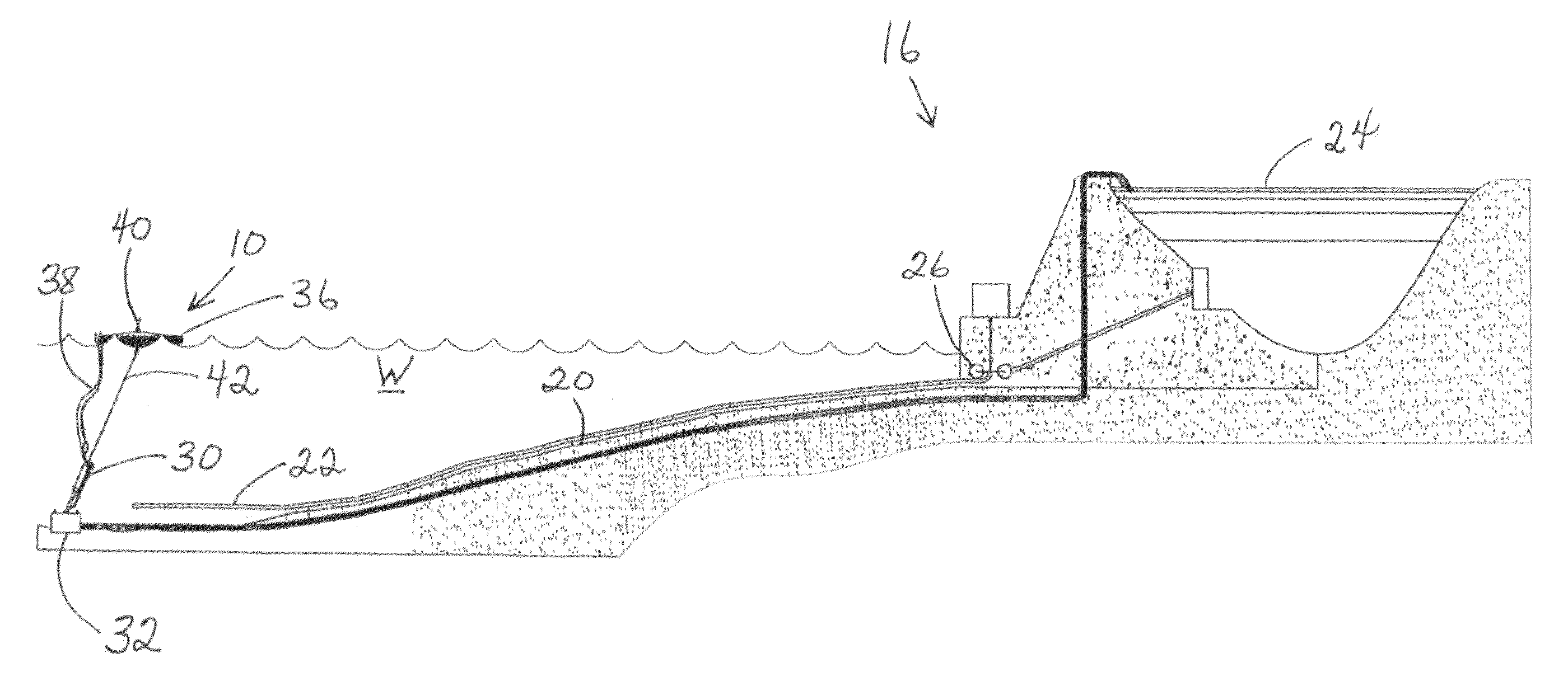
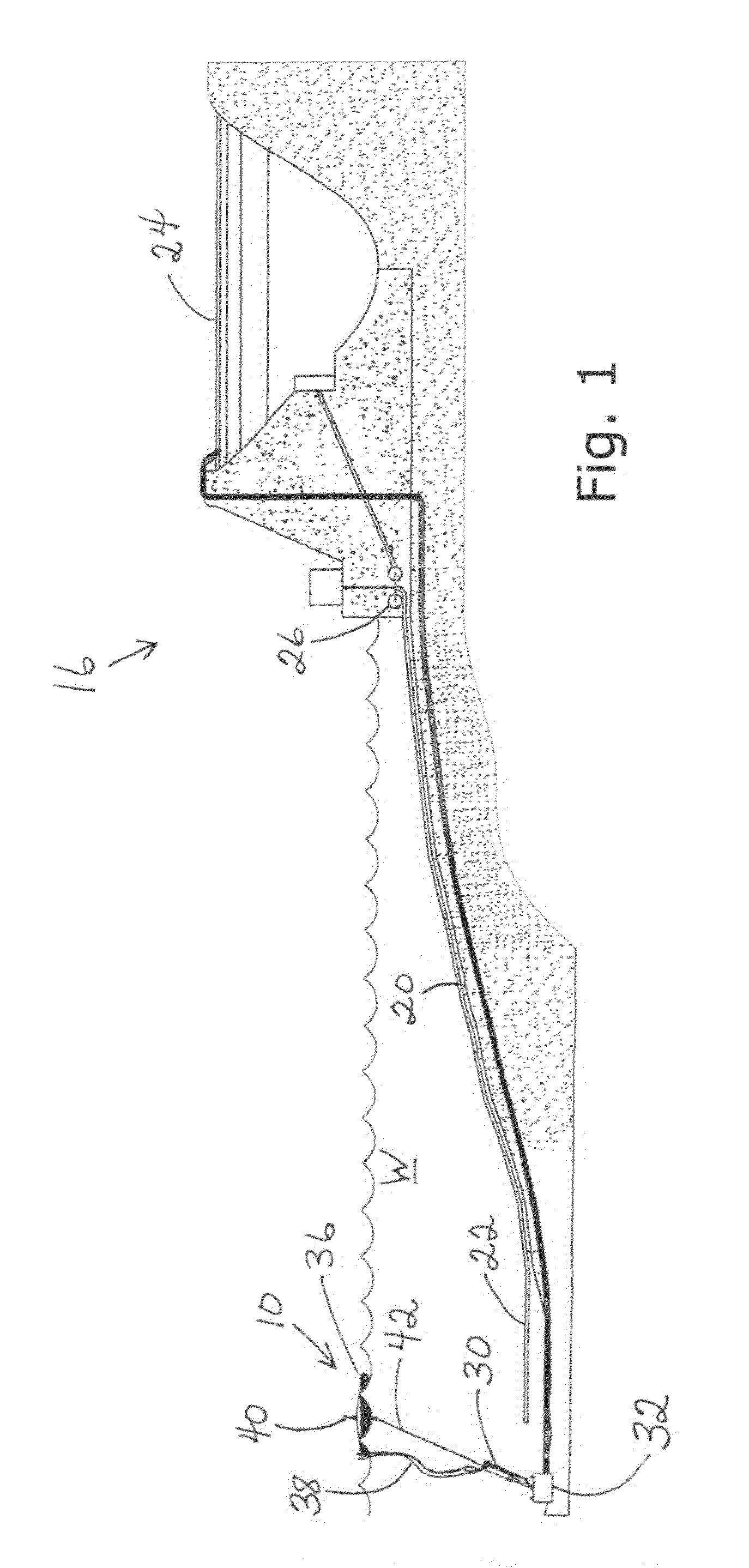
[0017]Referring to FIG. 1, a side elevation of the invention wave driven pump 30 and power generation station 16 is depicted installed in an ocean near the shoreline. As discussed above, an ocean site is preferred to harness the substantially continuous wave activity in driving the pump that is the central element of the present invention. However, it is recognized that major lakes also have significant wave action, therefore the term ocean is used in the context to include all bodies of water having fairly regular wave activity. A pumping station 10 is installed a distance from the shore where the water is of sufficient depth for proper pump operation, e.g. approximately seventy-five feet deep. A power generation station 16 is installed on shore to receive a flow of pressurized water from pump 30 through pipe 20. Power generation station 16 may be located adjacent to the ocean shore or farther inland, depending on the topography and local regulations, etc.

[0018]Referring further to...


PUM


Abstract

A piston pump is anchored to the ocean floor with the piston rod connected to a float that rides on the surface waves. The pump connects to a sparge line that discharges a spray of water through the float to indicate proper pump function. The float is formed with a conical upper portion and a conical lower portion and has an annular resilient rim. An array of pumps sends water under pressure through an aquaduct to an onshore electric power generation station, optionally including a reservoir. Water is returned from the generation station to the vicinity from which it was pumped.

Description

RELATED APPLICATION[0001]This application is a conversion of provisional patent application No. 61 / 270,939 filed Jul. 15, 2009.FIELD OF THE INVENTION[0002]The present invention relates to the field of power generation, and more particularly to a system for using wave motion to operate a pump for storing energy and providing water to generate electric power hydroelectrically.BACKGROUND OF THE INVENTION[0003]The world demand for electric power increases continuously, partly because science and engineering develop more and better devices that rely on electricity, and partly because the world population grows every year. Most of the currently available electric power is generated by combustion of fossil fuels, i.e. oil, coal and natural gas. Burning these fuels presents two serious problems:1) the supply of fossil fuel is not endless and will, in the foreseeable future, be depleted, and2) the by-products of this burning pollute the atmosphere and have been found to cause climate change ...

Claims


Application Information

Patent Timeline
Patent Type & Authority Applications(United States)
IPC IPC(8): F03B13/18
CPCF03B13/06F03B13/18Y02E60/17Y02E10/38Y02E10/22Y02E10/20Y02E10/30Y02E60/16
Inventor VENTZ, GEORGE A.
Owner VENTZ GEORGE A
Why Eureka
Try Eureka