Control system for ac motor

a control system and ac motor technology, applied in the direction of electric generator control, dynamo-electric converter control, dynamo-electric gear control, etc., can solve the problem of difficulty in providing high output or power in a high-speed region, and achieve the effect of simple computation or calculation

Inactive Publication Date: 2011-10-13
TOYOTA JIDOSHA KK
View PDF10 Cites 41 Cited by
  • Summary
  • Abstract
  • Description
  • Claims
  • Application Information

AI Technical Summary

Benefits of technology

[0023]According to the present invention, the feed-forward control for changing the voltage phase of rectangular wave voltage applied to the AC motor based on the torque c...

Problems solved by technology

With the sinusoidal PWM control, however, a fundamental component of the output voltage of the inverter cannot be sufficiently raised and the voltage utilization factor is limited, which makes it difficult to provide high output or power in a high-speed region.
Generally, the output torque changes non-linearly with respect to the ...

Method used


Image

  • Control system for ac motor
  • Control system for ac motor
  • Control system for ac motor

Examples


first embodiment

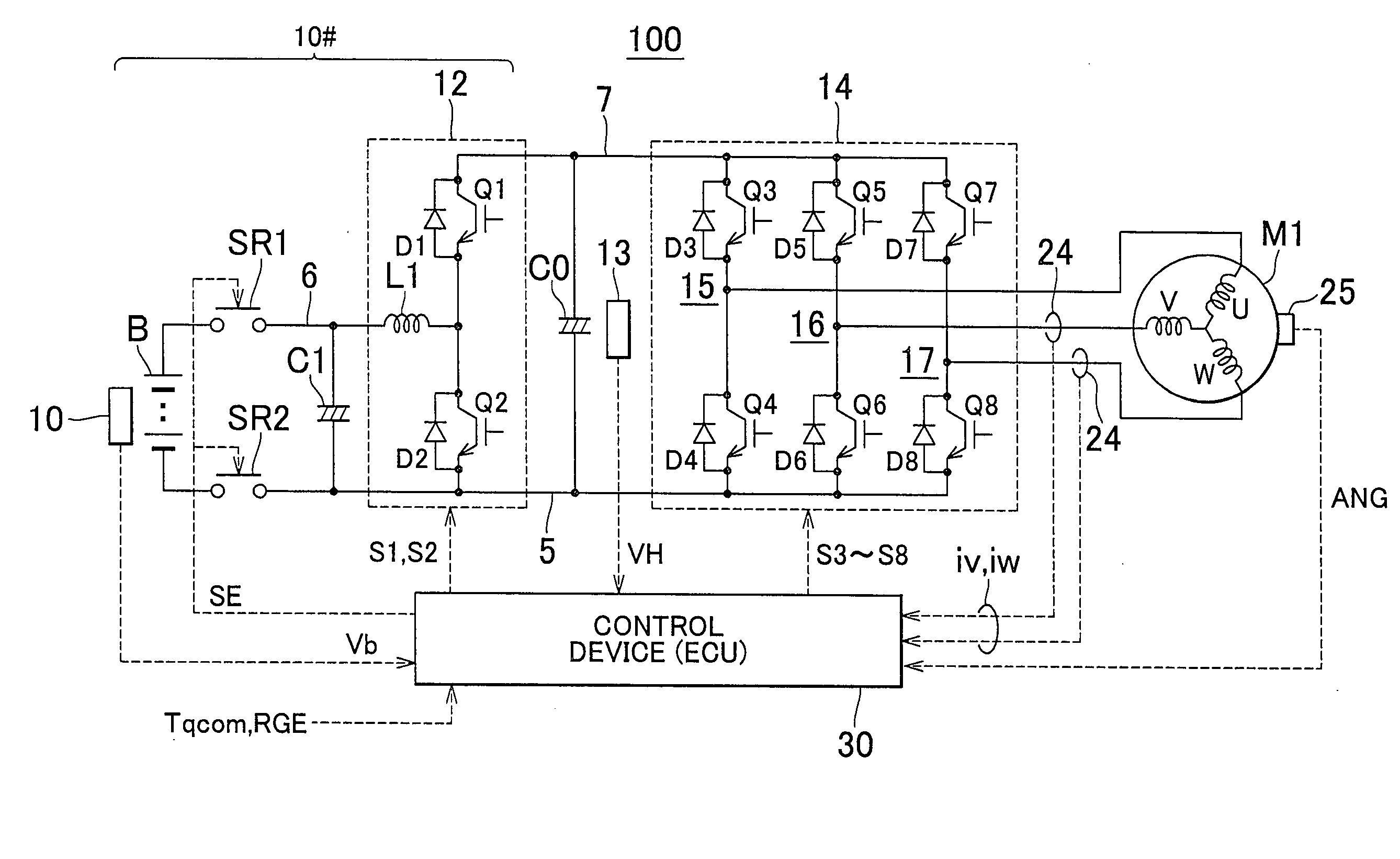
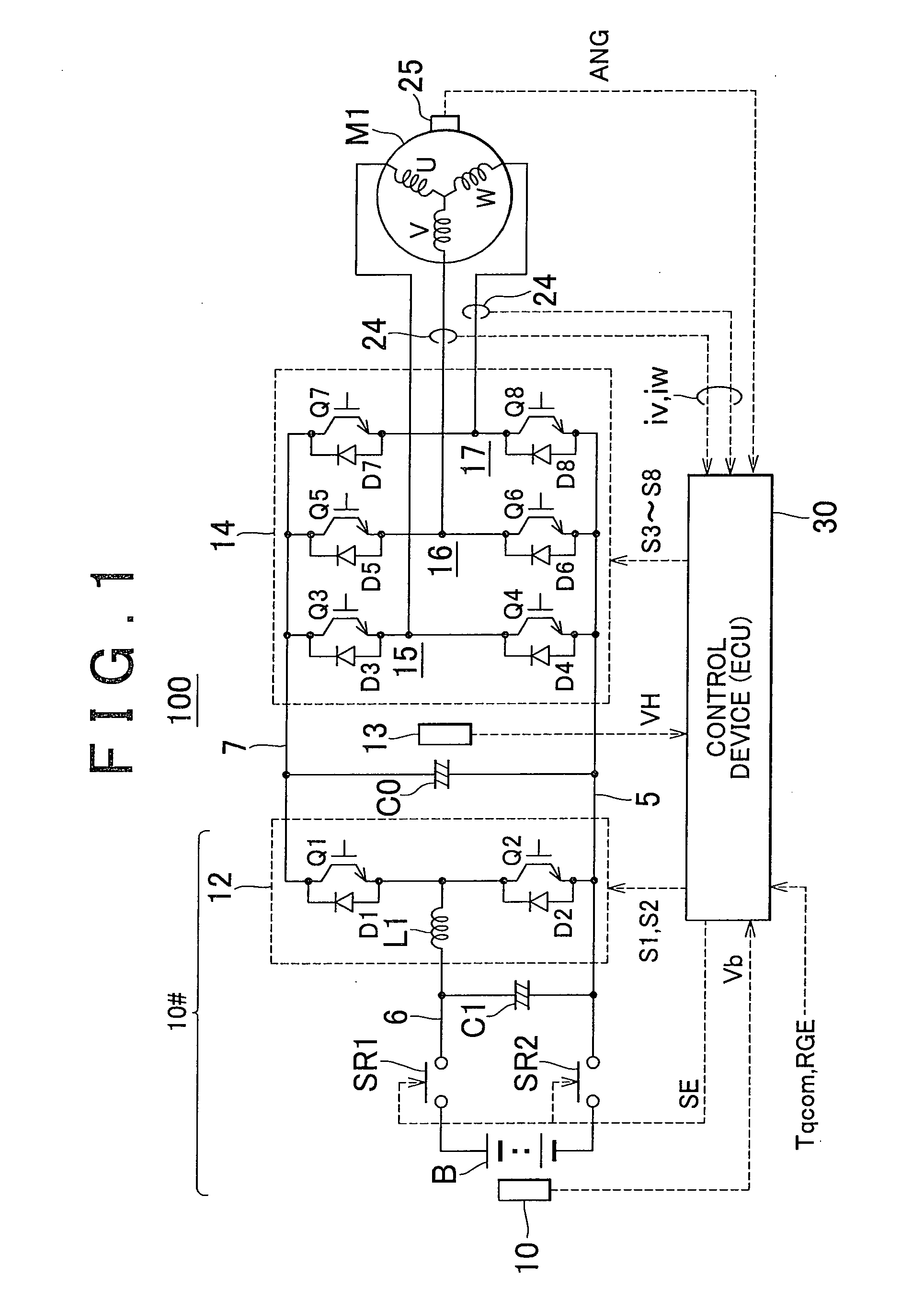
[0045]First Embodiment FIG. 1 shows the overall construction of a control system for an AC (alternating-current) motor according to the invention.

[0046]Referring to FIG. 1, a motor control system 100 includes a DC voltage generating portion 10#, a smoothing capacitor C0, an inverter 14, a control device 30 and an AC motor M1.

[0047]The AC motor M1 is an electric motor operable to generate torque for driving drive wheels of an electrically operated vehicle, such as a hybrid vehicle or an electric vehicle. In this embodiment, electrically operated vehicles include all types of vehicles on which an electric motor for generating wheel driving force, including an electric vehicle on which no engine is installed. The AC motor M1 is generally configured to have both the functions of a motor and a generator. When used in a hybrid vehicle, the AC motor M1 may be configured to have the function of a generator driven by the engine. Also, the AC motor M1 may be incorporated in a hybrid vehicle t...

first modified example

[0122 of the First Embodiment In the operation (FIG. 6) according to the first embodiment, the feed-forward term θff is calculated by obtaining the operating point Pc on the tangent TL, instead of the operating point Pb on the torque characteristic curve 500 which is to be primarily obtained, based on the slope of the tangent at the current operating point Pa on the torque characteristic curve 500. Accordingly, a large error may occur in the feed-forward term θff set in the above manner, since a difference between the operating points Pb and Pc may become large due to a difference between the slopes of the tangents at the operating points Pa, Pb, depending on the region of the voltage phase concerned.

[0123]In the first modified example of the first embodiment, therefore, a method of calculating the feed-forward term θff with improved accuracy, namely, an operation to make the feed-forward term θff closer to a difference (θ0-θ0#) in voltage phase between the current operating point P...

second modified example

[0132]Second Modified Example of the First Embodiment In the first embodiment, a method for determining the feed-forward term θff with even higher accuracy will be described.

[0133]FIG. 11 is a graph useful for explaining calculation of an integral term shift amount in rectangular wave voltage control according to the second modified example of the first embodiment.

[0134]Referring to FIG. 11, in the second modified example of the first embodiment, the operating point Pe is obtained in the same manner as in the first modified example of the first embodiment, and then an operating point Pf (torque value T3) that lies on the torque characteristic curve 500 and has the same voltage phase θ2 as the operating point Pe is further obtained.

[0135]Then, if a torque difference |T3−Tqcom| is equal to or larger than a predetermined value, the slope k′ of a straight line 530 that passes the operating points Pa and Pf is obtained, and the operating point Pe is updated to an operating point that lie...


PUM


Abstract

A control system for an AC motor determines a slope Ktl of a tangent TL at an operating point Pa corresponding to the current motor operating state and voltage phase (θ0) on a torque characteristic curve that is plotted according to a torque equation representing an output torque characteristic with respect to the motor operating state and the voltage phase of the rectangular wave voltage. The control system further calculates a voltage phase change amount θff for use in feed-forward control, according to ΔTtl/Ktl obtained by dividing a torque compensation amount ΔTtl for feed-forward control by the slope Ktl.

Description

BACKGROUND OF THE INVENTION[0001]1. Field of the Invention[0002]The invention relates to a control system for controlling an AC motor, and more particularly to a motor control system that converts DC voltage into rectangular wave AC voltage by means of an inverter, and applies the AC voltage to the AC motor.[0003]2. Description of the Related Art[0004]A motor control system is generally used which converts DC voltage into AC voltage via an inverter and applies the AC voltage to the AC motor so as to drive the motor under control. In the motor control system of this type, motor current is generally controlled according to sinusoidal pulse width modulation (PWM) control based on vector control, so as to drive the AC motor with high efficiency.[0005]With the sinusoidal PWM control, however, a fundamental component of the output voltage of the inverter cannot be sufficiently raised and the voltage utilization factor is limited, which makes it difficult to provide high output or power in...

Claims


Application Information

Patent Timeline
IPC IPC(8): H02P23/00H02P27/06B60L9/18B60L50/13B60L50/16H02P21/00H02P21/22H02P23/28H02P25/026H02P27/08H02P29/00H02P29/20H02P29/40
CPCB60L11/08H02P21/0021H02P23/0027H02P23/0086H02P23/009H02P25/021Y02T10/70H02P27/06H02P2201/09H02P2205/05Y02T10/643Y02T10/7077H02P27/02H02P25/024B60L50/13Y02T10/64Y02T10/7072
Inventor YAMAKAWA, TOSHIFUMIYAMADA, KENJIONO, TOSHIKAZU
Owner TOYOTA JIDOSHA KK
Why Eureka
Try Eureka