Stored Compressed Air Management and Flow Control for Improved Engine Performance

a compressed air and storage technology, applied in the direction of electric control, ignition automatic control, combustion air/fuel air treatment, etc., can solve the problems of undesirable power lag, torque may not be available, power, fuel efficiency, emissions-control performance of a boosted engine may suffer, etc., to achieve greater fuel efficiency, lower emissions, and power. the effect of reducing emissions

Inactive Publication Date: 2011-10-20
FORD GLOBAL TECH LLC
View PDF8 Cites 14 Cited by
  • Summary
  • Abstract
  • Description
  • Claims
  • Application Information

AI Technical Summary

Benefits of technology

[0006]The inventors herein have further recognized that a properly configured compressed-air management system can be used to address the transient-control issues identified above. Therefore, one embodiment provides a method for providing air to a combustion chamber of an engine, the engine including a compressor and a boost tank selectably coupled to an intake manifold. The method comprises admitting air from the compressor to the intake manifold via a main throttle valve, storing some air from the compressor in a boost tank, and discharging some of the air stored in the boost tank to the intake manifold via an auxiliary throttle valve distinct from the main throttle valve. The dual-throttle, boost-tank approaches described here offer improved flexibility in purging exhaust-diluted air from the intake manifold during closed-throttle conditions. In some embodiments, these approaches amplify the effective amount of compressed that can be obtained from a boost tank of a given volume.

Problems solved by technology

During transient conditions, however, the power, fuel efficiency, and emissions-control performance of a boosted engine may suffer.
Such torque may not be available, however, if the turbine that drives the compressor is not fully spun up.
As a result, an undesirable power lag may occur before the intake air flow builds to the required level.
However, the inventors herein have recognized that other transient control issues may occur during decreasing engine load.
Such actions erode fuel efficiency, however, as the mechanical energy used to compress the air charge is wasted when the air is released to the atmosphere.
Moreover, in engine systems equipped with low-pressure (LP) exhaust-gas recirculation (EGR), merely opening the by-pass valve may not adequately prepare the engine for low-load operation.
During closed-throttle conditions, however, non-diluted, fresh air may be required for reliable combustion.
It will be noted that the engine system disclosed in U.S. Pat. No. 5,064,423 is unthrottled, and therefore does not address the particular transient-control issues noted above.
Further, it does not contemplate the broad range of throttle-valve configurations that may be used to address them.

Method used


Image

  • Stored Compressed Air Management and Flow Control for Improved Engine Performance
  • Stored Compressed Air Management and Flow Control for Improved Engine Performance
  • Stored Compressed Air Management and Flow Control for Improved Engine Performance

Examples


Embodiment Construction

[0020]The subject matter of this disclosure is now described by way of example and with reference to certain illustrated embodiments. Components, process steps, and other elements that may be substantially the same in one or more embodiments are identified coordinately and are described with minimal repetition. It will be noted, however, that elements identified coordinately may also differ to some degree. It will be further noted that the drawing figures included in this disclosure are schematic and generally not drawn to scale. Rather, the various drawing scales, aspect ratios, and numbers of components shown in the figures may be purposely distorted to make certain features or relationships easier to see.

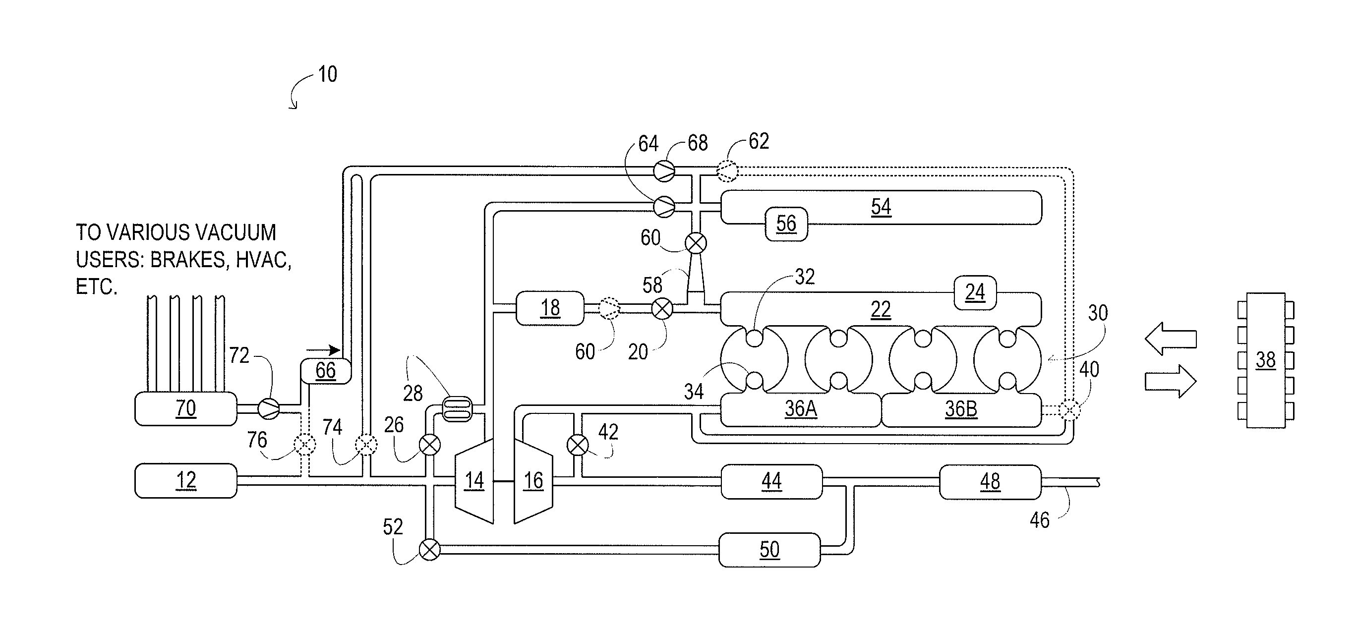
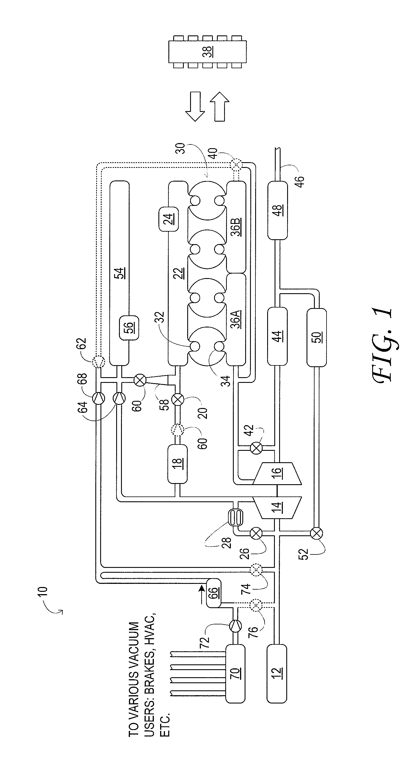
[0021]FIG. 1 schematically shows aspects of an example engine system 10 in one embodiment. In engine system 10, fresh air is introduced via air cleaner 12 and flows to compressor 14. The compressor may be any suitable intake-air compressor—a motor-driven or driveshaft driven supe...


PUM


Abstract

A method for providing air to a combustion chamber of an engine, the engine including a compressor and a boost tank selectably coupled to an intake manifold. The method comprises admitting air from the compressor to the intake manifold via a main throttle valve, storing some air from the compressor in a boost tank, and discharging some of the air stored in the boost tank to the intake manifold via an auxiliary throttle valve distinct from the main throttle valve.

Description

TECHNICAL FIELD[0001]This application relates to the field of motor-vehicle engineering, and more particularly, to air induction in motor vehicle engine systems.BACKGROUND AND SUMMARY[0002]A boosted engine may offer greater fuel efficiency and lower emissions than a naturally aspirated engine of similar power. During transient conditions, however, the power, fuel efficiency, and emissions-control performance of a boosted engine may suffer. Such transient conditions may include rapidly increasing or decreasing engine load, engine speed, or mass air flow. For example, when the engine load increases rapidly, a turbocharger compressor may require increased torque to deliver an increased air flow. Such torque may not be available, however, if the turbine that drives the compressor is not fully spun up. As a result, an undesirable power lag may occur before the intake air flow builds to the required level.[0003]It has been recognized previously that a turbocharged engine system may be ada...

Claims


Application Information

Patent Timeline
Patent Type & Authority Applications(United States)
IPC IPC(8): F02D9/08F02B33/00
CPCB60T17/06F02B33/44F02B29/0418F02B29/0425F02B29/0437F02B29/06F02B37/00F02D37/02F02D41/0007F02D41/0065F02D41/18F02D2041/0022F02D2200/0406F02M25/0709F02M25/0713F02M25/0718F02M25/0727F02M25/0752F02M35/08F02M35/10163F02M35/10229F02P5/045Y02T10/146Y02T10/144Y02T10/47F02B29/04F02B21/02F02M26/06F02M26/10F02M26/15F02M26/23F02M26/01Y02T10/12Y02T10/40
Inventor PURSIFULL, ROSS DYKSTRAULREY, JOSEPH NORMAN
Owner FORD GLOBAL TECH LLC
Why Eureka
Try Eureka