Biofuel production method and system

a biofuel and production method technology, applied in biofuels, fuels, pressurized chemical processes, etc., can solve the problems of affecting the engine, slowing down, and generating a lot of energy

Active Publication Date: 2011-10-27
GER ENTERPRISES
View PDF7 Cites 12 Cited by
  • Summary
  • Abstract
  • Description
  • Claims
  • Application Information

AI Technical Summary

Problems solved by technology

Thus, transesterification typically proceeds slowly and generates a great deal of glycerol and some water which must be removed from the biofuel before it can be used.
If not removed, any of these byproducts may prevent the biofuel from being burned in a combustion engine or the byproducts may cause harm to the engine.
However, hydrotreating has less desirable cold flow properties.

Method used


Image

  • Biofuel production method and system
  • Biofuel production method and system
  • Biofuel production method and system

Examples


Embodiment Construction

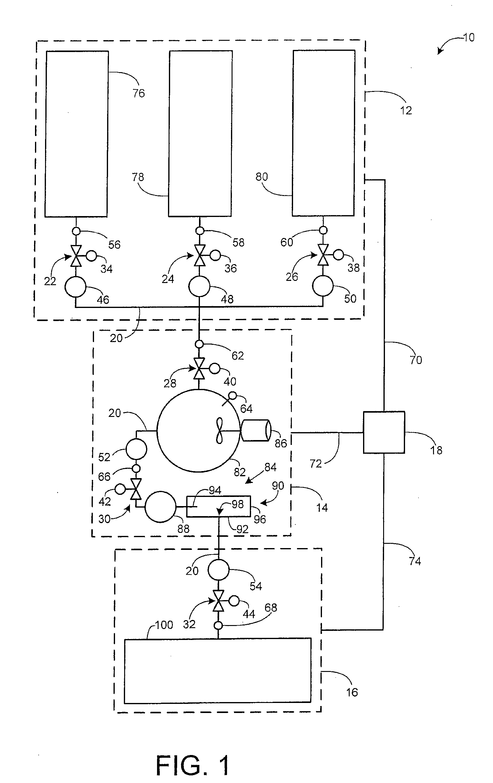
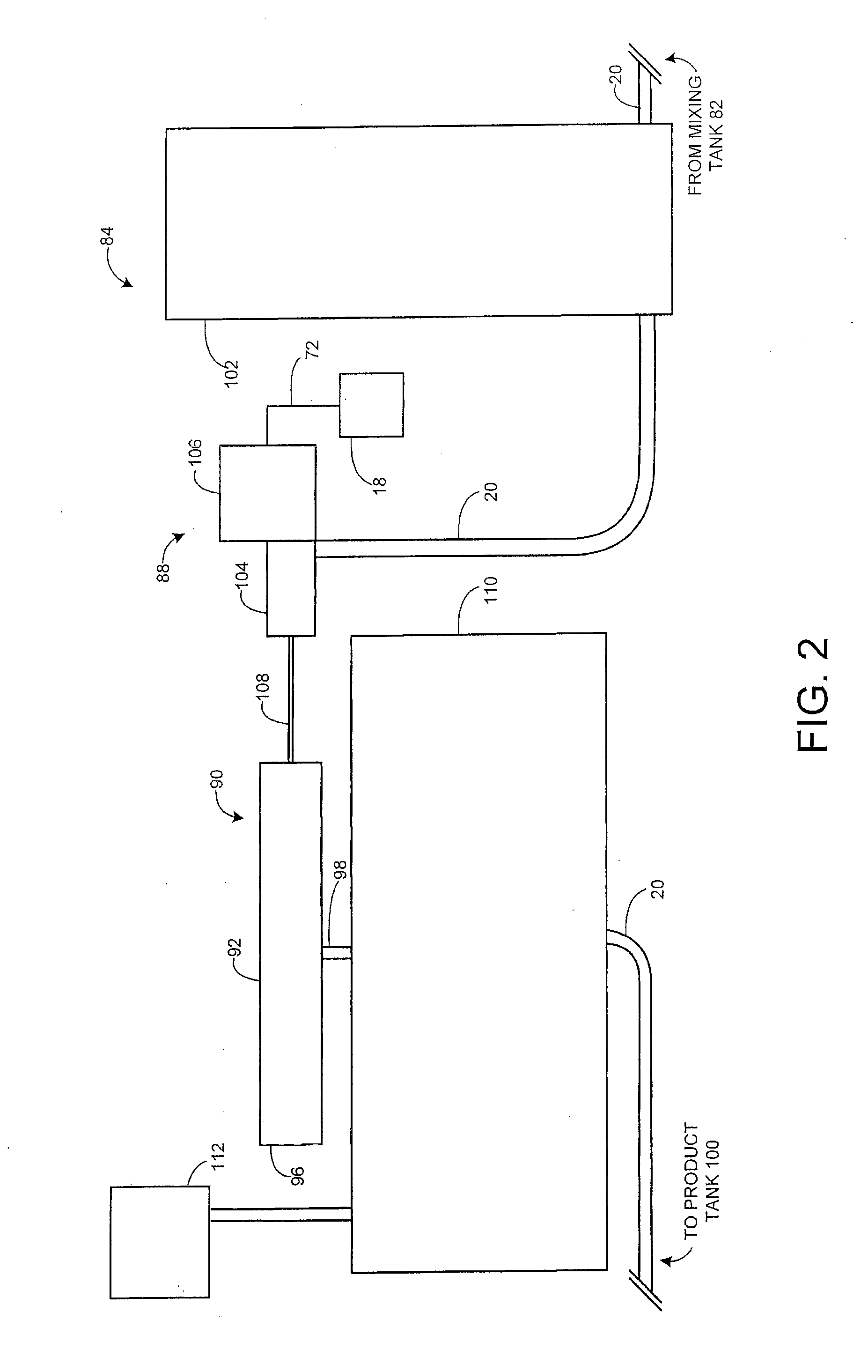
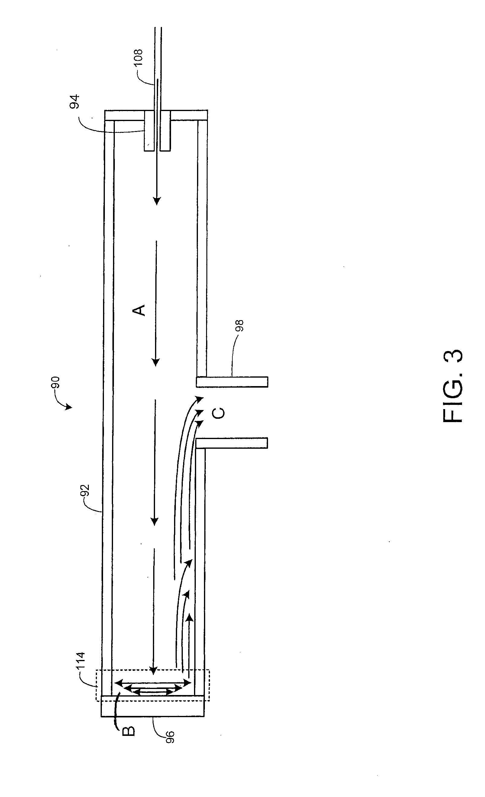
The present invention provides, in some embodiments, a biofuel manufacturing system and a method of manufacturing biofuels. In an embodiment, the invention provides a biofuel manufacturing system for manufacturing various biofuels such as, for example, biodiesel, biofuel oil, bio gasoline or petrol, and the like. In this regard, the term ‘bio’ refers to the biologically derived nature of at least some portion of the fuel manufactured. Advantages of certain embodiments of the biofuel manufacturing system include one or more of: processing a flow of biofuels; scalability; reducing production costs; reducing byproducts and costs associated with byproduct removal; increasing production rate; and the like. As a result of these advantages, the biofuel manufacturing system may generate a finished biofuel from raw materials in a relatively compact space and in a relatively short amount of time as compared to conventional manufacturing systems.

In addition, the present biofuel manufacturing s...


PUM


Abstract

In an embodiment of the present invention, a renewable energy fuel is prepared by a process including the steps of: a) providing a renewable energy feedstock; b) providing an alcohol; c) providing a catalyst; d) mixing (a), (b), and (c) to form a blend; and e) homogenizing the blend at a pressure greater than 400 kilogram-force per square centimeter (Kg / cm2).

Description

FIELD OF THE INVENTIONThe present invention generally relates to the manufacture of fuel. More particularly, the present invention pertains to a method, device and system for manufacturing renewable biofuel.BACKGROUND OF THE INVENTIONBiodiesel is produced via a reaction of vegetable oil or animal fat with an alcohol (usually methanol) and a catalyst. Biodiesel is chemically distinct from petroleum diesel and has a separate ASTM standard (D6751), which specifies the standard for biodiesel for use as a blend component with petroleum diesel. As approved by the United States Environmental Protection Agency, (“EPA”), the manufacture of biofuel has involved two conventional processes: transesterification and hydrotreating.Transesterification involves the chemical replacement of glycerol in a triglyceride with an ester of an alcohol molecule. The process forms two principal products, fatty acid methyl esters or FAME, the chemical name for biodiesel, and glycerin. In this reaction, a vegeta...

Claims


Application Information

Patent Timeline
Patent Type & Authority Applications(United States)
IPC IPC(8): C10L1/00B01J19/00
CPCB01J3/02B01J3/04C10G1/08C10G3/42C10L1/02C10L1/026C10L1/00C11C3/003Y02E50/13C10L1/04C10G2300/1014C10G2300/1018B01J19/0066C10L1/19Y02P30/20Y02E50/10
Inventor HANSON, ARLISTHOMPKINS, ANTON ANGELOSEVER, NICHOLAS JOSEPHPETERSON, RICHARD LEEICE, LUKE CHRISTOPHER
Owner GER ENTERPRISES
Why Eureka
Try Eureka