System and method for construction of a floor slab and a roof slab

Inactive Publication Date: 2011-10-27
SULTAN JAVED
View PDF1 Cites 3 Cited by
  • Summary
  • Abstract
  • Description
  • Claims
  • Application Information

AI Technical Summary

Benefits of technology

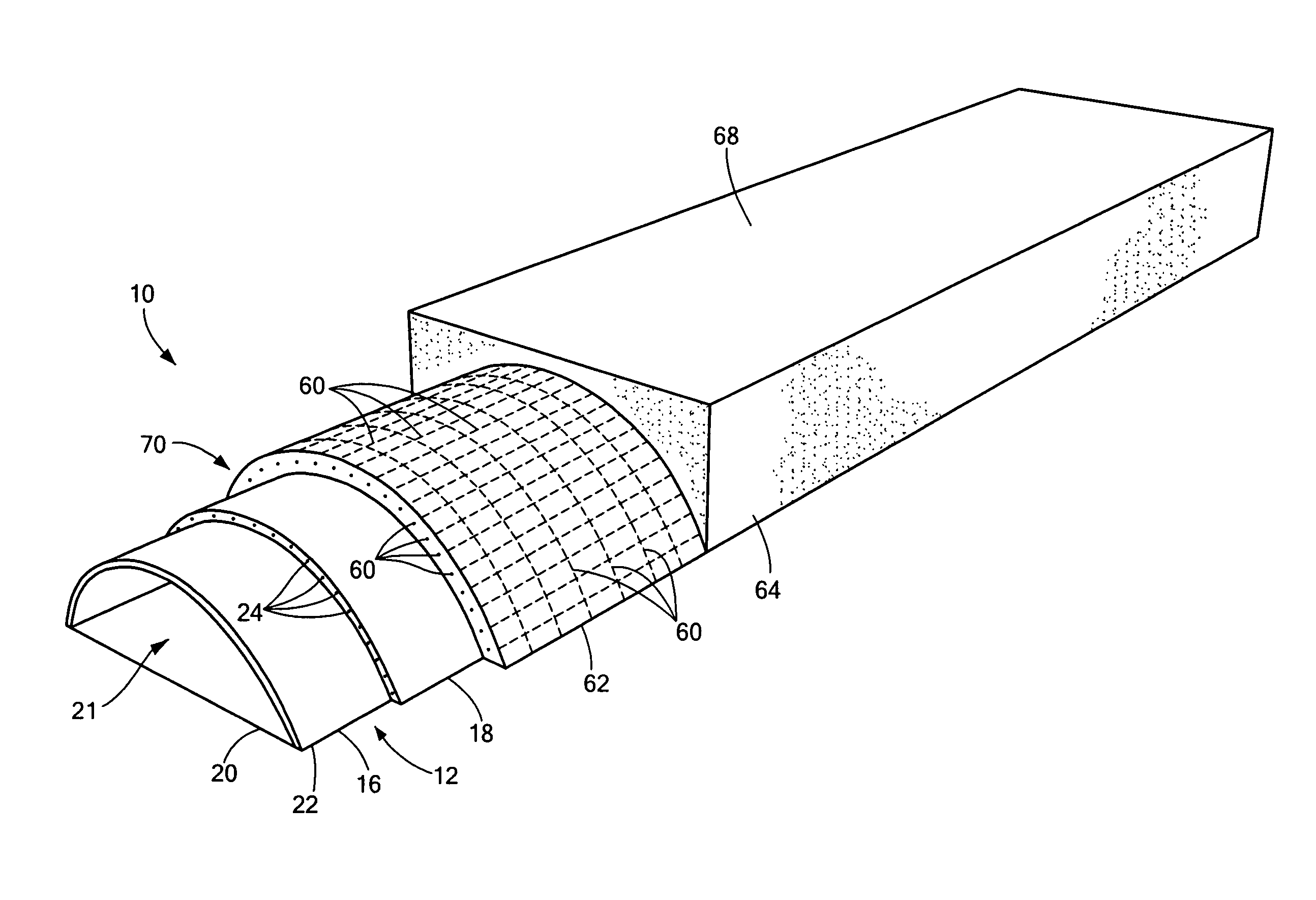
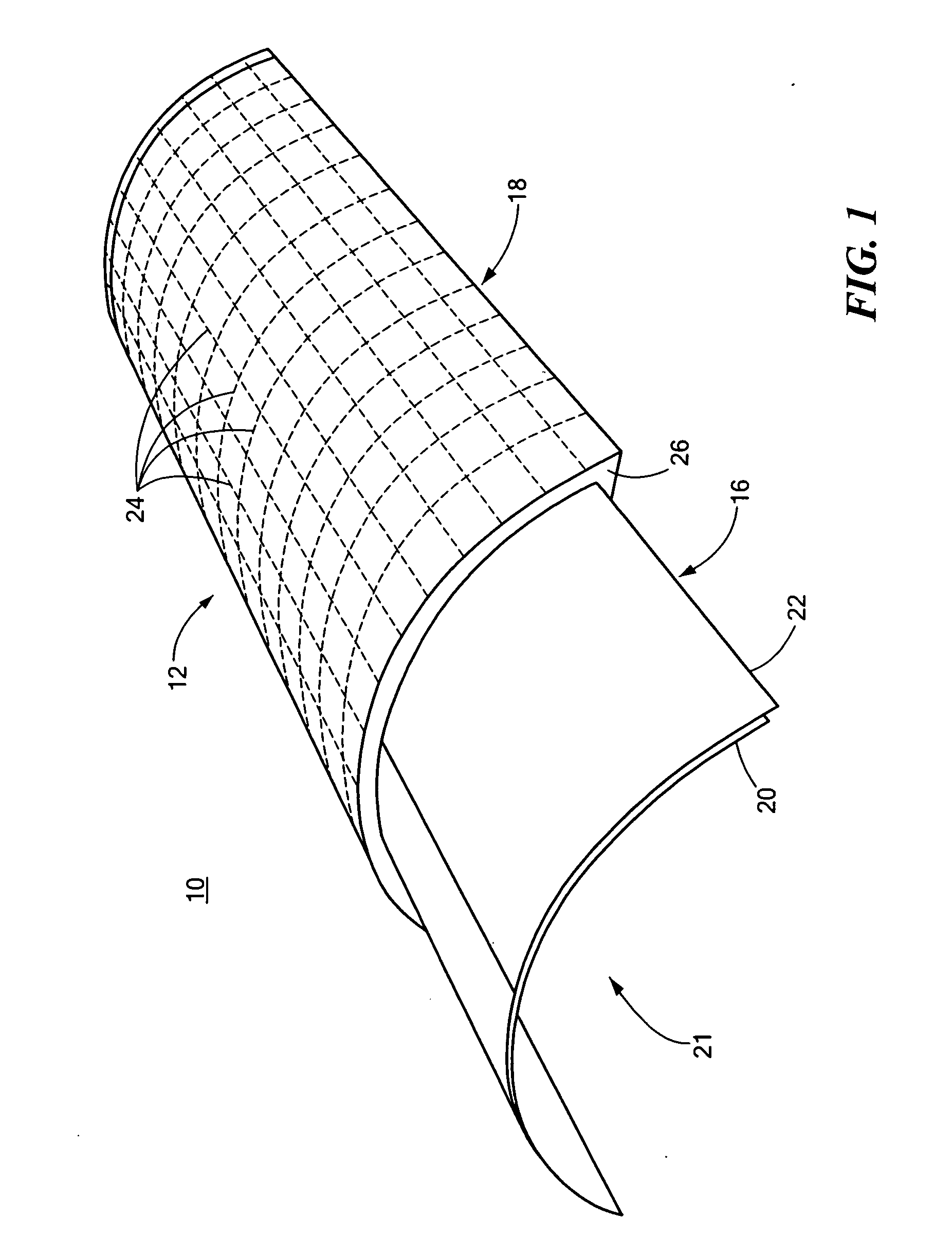
[0005]In one embodiment, the first skin may include a flexible membrane configured to form the predetermined shape. The predetermined shape may include a parabolic, semi-circular shape, a hyperbola shape, a dome shape, or a non-symmetrical parabolic shape. The flexible membrane may be made one or more of: steel mesh, plastic fabric, epoxy fabric, composite fabric, carbon fabric, and organic fabric. The gage of the flexible membrane layer may be configured to improve strength and spanning capabilities of the floor slab or the roof slab. The first skin may include a thin coating of a reinforcing material over the flexible membrane. The reinforcing material may include one or more of: concrete, epoxy, cementitious plaster, or a composite material including inorganic and / or organic resins forming a bonding material. The predetermined shape of the first skin may form a void. The second skin may include reinforcing bars configured to improve strength and spanning capabilities of the floor slab or the roof slab. The second skin may include a thin coating of a reinforcing material configured to embed the reinforcing bars therein and improve strength and spanning capabilities of the floor slab or the roof slab. The reinforcing material may include cement, coarse sand, and coarse gravel. The system may include a finish skin over the starter mold. The floor slab or the roof slab may be configured to span a floor or roof opening having a length in the range of about six inches to about 18 feet to about 24 feet. The system may include a third skin attached to the starter mold configured to reinforce the starter mold. The system may include a fourth skin attached to the third skin configured to reinforce the starter mold. The third skin may include reinforcing bars configured to improve strength and spanning capabilities of the floor slab or the roof slab. The fourth skin may include a thin film coating of a reinforcing material configured to embed the reinforcing bars therein and improve strength and spanning capabilities of the floor slab or the roof slab. The reinforcing material may include concrete. The system may include a finish skin over the fourth skin. The floor slab or the roof slab may be configured to span a floor or roof opening having a length greater than about 18 feet to about 24 feet. The system may include a casting subsystem configured to create the starter mold. The casting subsystem may include a frame, and a flexible membrane attached to the top of the box frame configured to form a mold having a predetermined shape for creating the first skin. The predetermined shape may include a parabolic, semi-circular shape, a hyperbola shape, a 
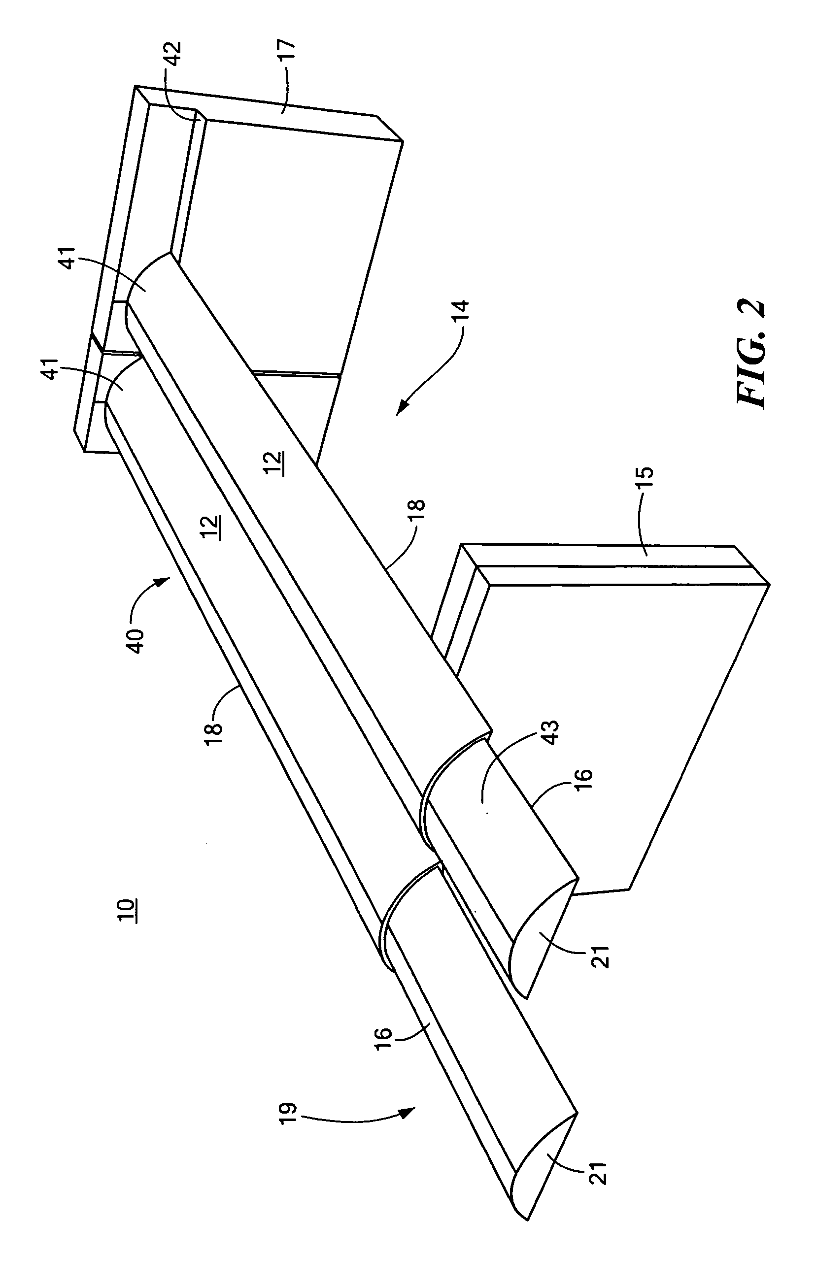
dome shape, or a non-symmetrical parabolic shape. The system may include a plurality of starter molds placed between a floor or roof opening configured to form a composite slab which defines the floor slab or the roof slab. The floor slab or the roof slab may be configured as an inclined diaphragm.

Problems solved by technology

The floor and roof slab pose special challenge in that a thin diaphragm is required to take loads perpendicular to its primary axis, e.g., the horizontal plane or at some specified inclination to the horizontal axis.
Considerable effort and expense go into placing the support system to enable curing and removal of same after the slab is cured.
Moreover, the area below the floor or roof slab cannot be utilized until the floor or roof slab has cured to the desired strength.
This wastes time and money.

Method used


Image

  • System and method for construction of a floor slab and a roof slab
  • System and method for construction of a floor slab and a roof slab
  • System and method for construction of a floor slab and a roof slab

Examples


Embodiment Construction

[0017]Aside from the preferred embodiment or embodiments disclosed below, this invention is capable of other embodiments and of being practiced or being carried out in various ways. Thus, it is to be understood that the invention is not limited in its application to the details of construction and the arrangements of components set forth in the following description or illustrated in the drawings. If only one embodiment is described herein, the claims hereof are not to be limited to that embodiment. Moreover, the claims hereof are not to be read restrictively unless there is clear and convincing evidence manifesting a certain exclusion, restriction, or disclaimer.

[0018]There is shown in FIG. 1 one embodiment of system 10 and the method thereof for the construction of a floor slab and / or a roof slab. System 10 includes starter mold 12 configured to span a floor or roof opening, e.g., floor opening 14, FIG. 2, between walls 15 and 17. Starter mold 12 may also span more than two walls,...


PUM

PropertyMeasurementUnit
Lengthaaaaaaaaaa
Lengthaaaaaaaaaa
Lengthaaaaaaaaaa

Abstract

This invention features a system for construction of a floor or roof slab. The system includes a starter mold configured to span a floor opening or a roof opening. The starter mold includes a first skin configured to form a diaphragm and a second skin attached to the first skin configured to reinforce the first skin.

Description

RELATED APPLICATIONS[0001]This application hereby claims the benefit of and priority to U.S. Provisional Application Ser. No. 61 / 343,267, filed on Apr. 26, 2010 under 35 U.S.C. §§119, 120, 363, 365, and 37 C.F.R. §1.55 and §1.78, incorporated by reference herein.FIELD OF THE INVENTION[0002]This invention relates to a system and method for the construction of a floor slab and a roof slab.BACKGROUND OF THE INVENTION[0003]Structures, such as walls, roof slabs, floor slabs, columns, supports, foundations, and the like, are typically manufactured using one or more of a variety of materials, such as wood, steel, reinforced concrete, brick, mud, and the like. Such structures are typically built to not only support the required dead loads and various type of live loads but oftentimes such structures must withstand wind loads and loads from earthquakes or other natural disasters. The floor and roof slab pose special challenge in that a thin diaphragm is required to take loads perpendicular t...

Claims


Application Information

Patent Timeline
IPC IPC(8): E04G11/36B29C33/42E04B1/02
CPCE04B5/38E04G11/36E04B7/08
Inventor SULTAN, JAVED
Owner SULTAN JAVED
Why Eureka
Try Eureka