System and methods for optimizing efficiency of a hydraulically actuated system

a technology energy efficiency, which is applied in the direction of fluid coupling, piston pump, servomotor, etc., can solve the problems of reducing the efficiency of hydraulic actuation system, so as to achieve the effect of increasing the gas pressur

Inactive Publication Date: 2011-10-27
GENERAL COMPRESSION
View PDF3 Cites 62 Cited by
  • Summary
  • Abstract
  • Description
  • Claims
  • Application Information

AI Technical Summary

Benefits of technology

[0010]Systems and methods for efficiently operating a hydraulically actuated device / system are described herein. For example, systems and methods for efficiently operating a gas compression and expansion energy storage system are disclosed herein. Systems and methods are provided for controlling and operating the hydraulic pumps / motors used within a hydraulically actuated device / system, such as, for example, a gas compression and / or expansion energy system, within a maximum efficiency range of the pumps throughout an entire cycle of the system. In such a system, a variety of different operating regimes can be used depending on the desired output gas pressure and the desired stored pressure of the compressed gas. Hydraulic cylinders used to drive working pistons within the system can be selectively actuated and / or can be actuated to achieve varying force outputs to incrementally increase the gas pressure, within the system for a given cycle.

Problems solved by technology

Electric power plants are also constrained in terms of how quickly they can start-up and shut-down, and it is commonly infeasible to completely shut-down a power plant.
The combination of power output constraints, and start-up and shut-down constraints, restricts a power plant's ability to optimally meet a fluctuating power demand.
These restrictions may lead to increased green house gas emissions, increased overall fuel consumption, and / or to potentially higher operating costs, among other drawbacks.
Existing energy storage technologies, however, have drawbacks.
By way of example, batteries, flywheels, capacitors and fuel cells may provide fast response times and may be helpful to compensate for temporary blackouts, but have limited energy storage capabilities and may be costly to implement.
Installations of other larger capacity systems, such as pumped hydro systems, require particular geological formations that might not be available at all locations.
Absent suitable energy storage systems, such intermittent power production sites may not be capable of operating at full capacity.
Electric power consumption sites, such as buildings, towns, cities, commercial facilities, military facilities, may have consumption that periodically exceeds electricity transmission capabilities.
Absent suitable energy storage systems, such power consumers may not be capable of operating at preferred levels.
Additionally or alternatively, air at pressures higher than 35 atmospheres may need to be throttled prior to expansion in the turbine, causing losses that reduce the efficiency of the system, and / or reduce the energy density that a storage structure may accommodate.
Additionally, to increase electrical energy produced per unit of air expanded through the turbine, compressed air in such systems is often pre-heated to elevated temperatures (e.g., 1000 C) prior to expansion by burning fossil fuels that both increases the cost of energy from the system and produces emissions associated with the storage of energy.
In such a system, however, the air may still achieve substantial temperatures during each stage of compression, prior to being cooled, which will introduce inefficiencies in the system.

Method used


Image

  • System and methods for optimizing efficiency of a hydraulically actuated system
  • System and methods for optimizing efficiency of a hydraulically actuated system
  • System and methods for optimizing efficiency of a hydraulically actuated system

Examples


Embodiment Construction

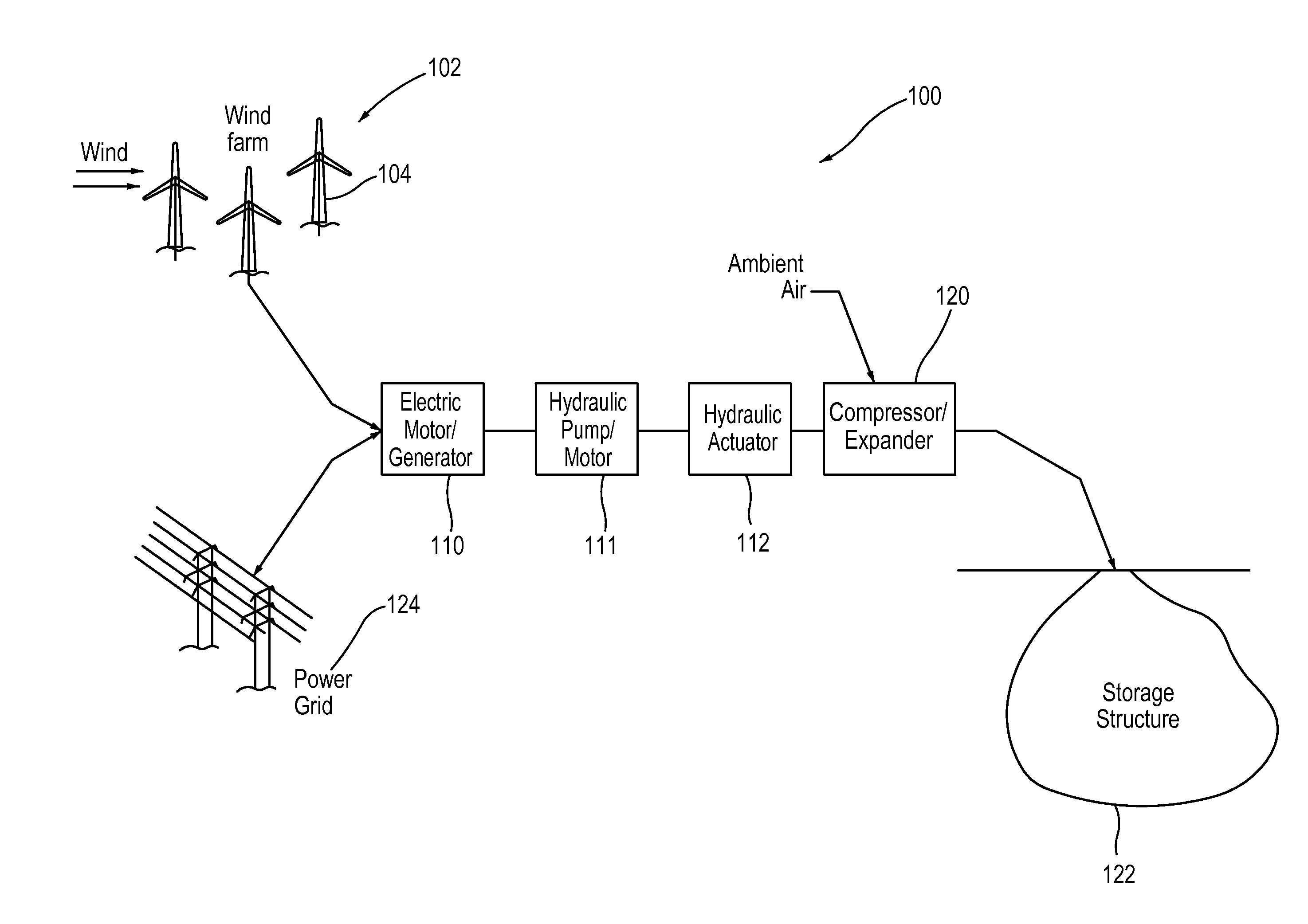
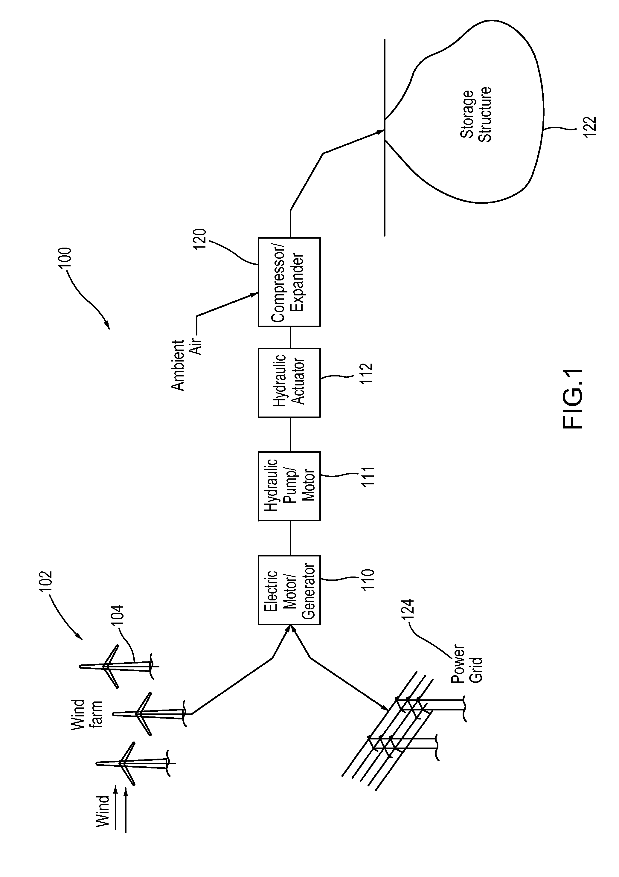
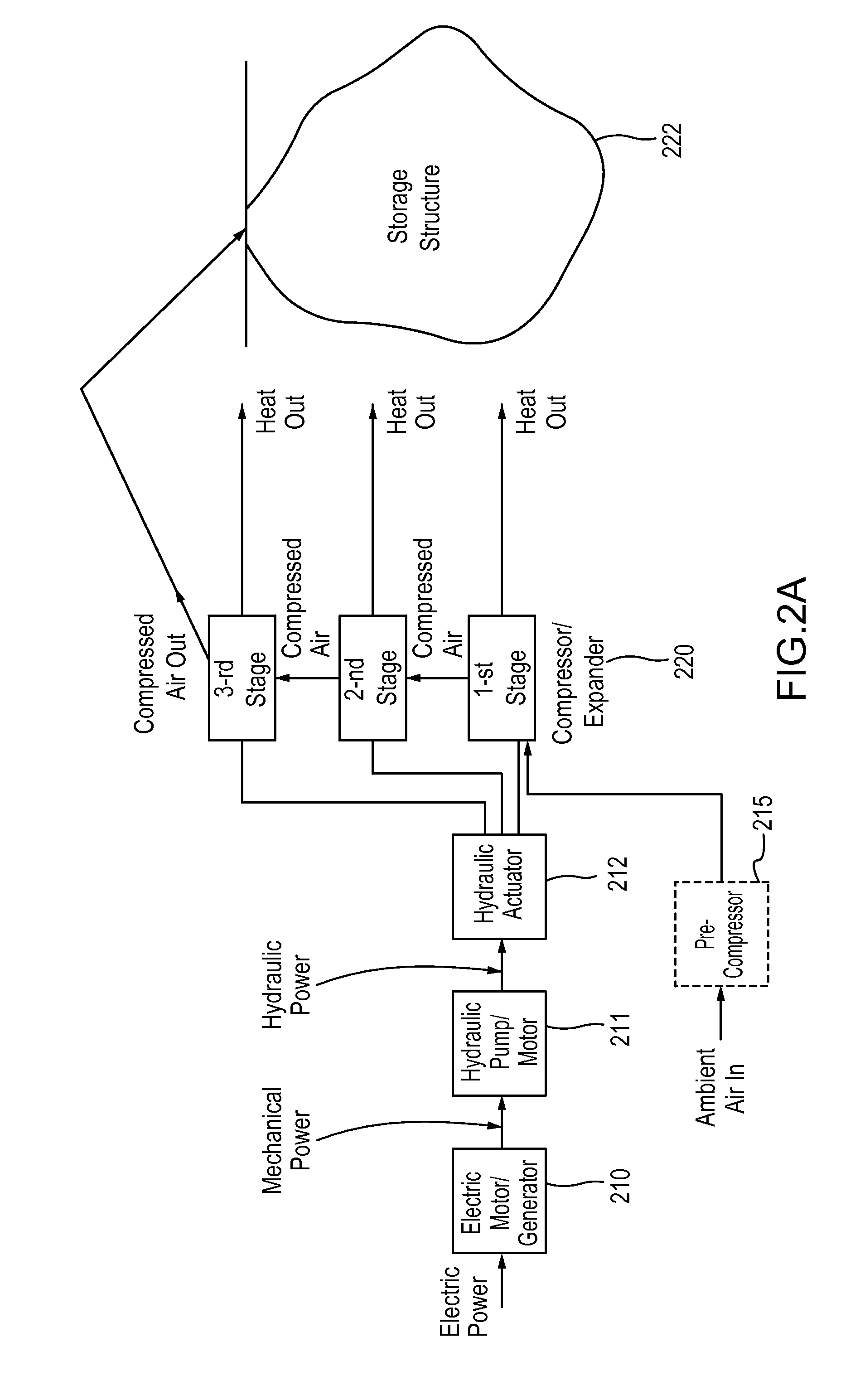
[0036]Systems and methods for efficiently operating a gas compression and / or expansion system are disclosed herein. The gas compression and / or expansion systems can use one or more hydraulic pumps / motors to move (or be moved by) gas and liquid within the system, and systems and methods are described herein to operate the hydraulic pump / motor in its most efficient regime, continuously or substantially continuously, during an operating cycle or stroke of the system. Hydraulic pumps can have efficient operating ranges that can vary as a function of, for example, flow rate and pressure, among other parameters. Systems and methods of operating the hydraulic pumps / motors are provided to allow them to function at an optimal efficiency throughout the stroke or cycle of the gas compression and / or expansion system.

[0037]As described herein, in some embodiments, hydraulic pumps / motors can be used to drive (or be driven by) a working piston within a gas compression and / or expansion system, in w...


PUM


Abstract

Systems and methods for efficiently operating a hydraulically actuated device/system are described herein. For example, systems and methods for efficiently operating a gas compression and expansion energy storage system are disclosed herein. Systems and methods are provided for controlling and operating the hydraulic actuators used within a hydraulically actuated device/system, such as, for example, a gas compression and/or expansion energy system, within a desired efficiency range of the hydraulic pump(s)/motor(s) used to supply or receive pressurized hydraulic fluid to or from the hydraulic actuators. In such a system, a variety of different operating regimes can be used depending on the desired output gas pressure and the desired stored pressure of the compressed gas. Hydraulic cylinders used to drive working pistons within the system can be selectively actuated to achieve varying force outputs to incrementally increase the gas pressure within the system for a given cycle.

Description

CROSS REFERENCE TO RELATED APPLICATIONS[0001]This application claims priority to and the benefit of U.S. Provisional Patent Application Ser. No. 61 / 290,107, filed Dec. 24, 2009, entitled “System and Methods for Optimizing Efficiency of a Hydraulically Actuated System,” the disclosure of which is hereby incorporated by reference in its entirety.BACKGROUND[0002]The invention relates generally to systems and methods of optimizing the energy efficiency of hydraulic actuation systems, for use in, for example, storing energy using a system and methods for optimizing the efficiency of a compressed air energy storage system.[0003]Traditionally, electric power plants have been sized to accommodate peak power demand. Moreover, electric power plant sizing must take into account their maximum power output, minimum power output, and a middle power output range within which they most efficiently convert fuel into electricity. Electric power plants are also constrained in terms of how quickly they...

Claims


Application Information

Patent Timeline
Patent Type & Authority Applications(United States)
IPC IPC(8): F15B3/00F15B15/18
CPCF02C6/16Y02T50/671Y02E60/15Y02E60/16Y02T50/60
Inventor INGERSOLL, ERIC D.ABORN, JUSTIN A.BLIESKE, MATTHEW
Owner GENERAL COMPRESSION
Why Eureka
Try Eureka