

R-Fe-B RARE-EARTH SINTERED MAGNET AND PROCESS FOR PRODUCING THE SAME
a rare-earth, sintered magnet technology, applied in the direction of magnets, magnet bodies, evaporation applications, etc., can solve the problems of difficult to obtain the expected crystal structure, ineffective coercivity,
- Summary
- Abstract
- Description
- Claims
- Application Information
AI Technical Summary
Benefits of technology
Problems solved by technology
Method used
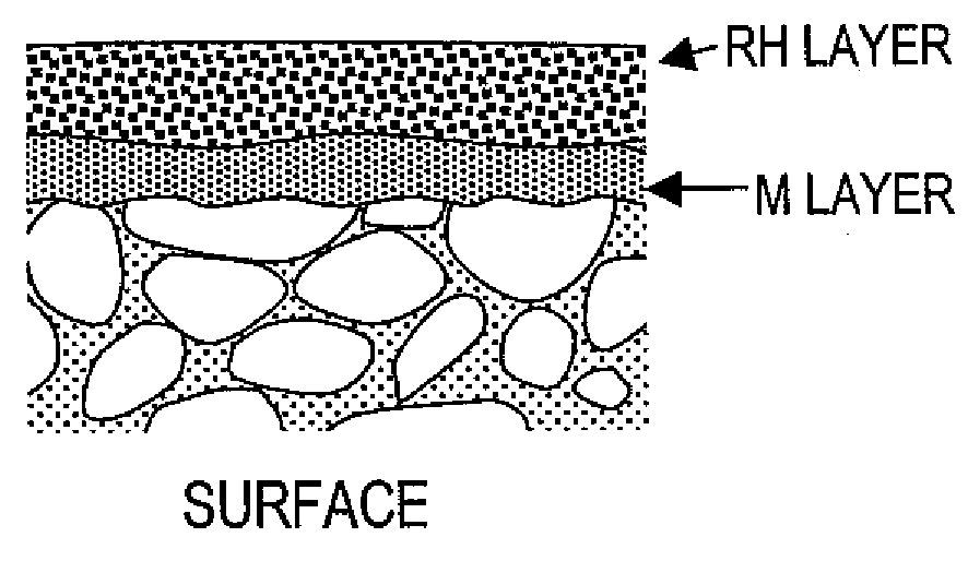
Image

Examples
example 1
[0068]An alloy ingot that had been prepared so as to have a composition consisting of about 14.6 at % of Nd, about 6.1 at % of B, about 1.0 at % of Co, about 0.1 at % of Cu, about 0.5 at % of Al and Fe as the balance was melted by a strip caster and then cooled and solidified, thereby making thin alloy flakes with thicknesses of about 0.2 mm to about 0.3 mm.
[0069]Next, a container was loaded with those thin alloy flakes and then introduced into a furnace for a hydrogen absorption, which was filled with a hydrogen gas atmosphere at a pressure of about 500 kPa. In this manner, hydrogen was occluded into the thin alloy flakes at room temperature and then released. By performing such a hydrogen process, the alloy flakes were decrepitated to obtain a powder in indefinite shapes with sizes of about 0.15 mm to about 0.2 mm.
[0070]Thereafter, about 0.05 wt % of zinc stearate was added to the coarsely pulverized powder obtained by the hydrogen process and then the mixture was pulverized with ...
examples 2 to 6
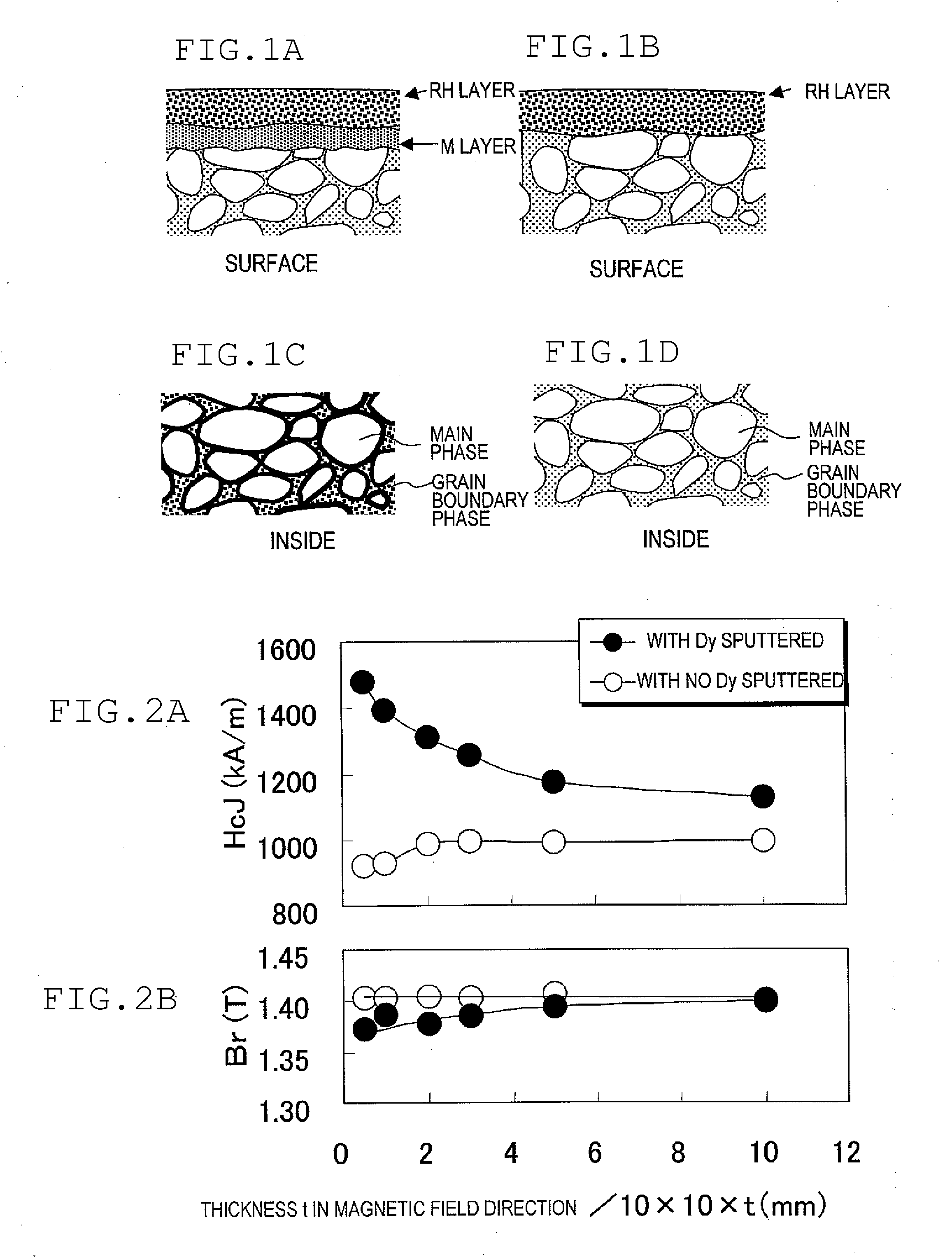
[0082]First, by performing the same manufacturing process steps as those of the first specific example described above, a number of sintered magnet bodies with a thickness of about 5 mm, a length of about 10 mm and a width of about 10 mm were made. Next, on each of these sintered magnet bodies, an Al, Bi, Zn, Ag or Sn layer was deposited to a thickness of about 2 μm, about 0.6 μm, about 1.0 μm, about 0.5 μm or about 1.0 μm, respectively, by a sputtering process.
[0083]Thereafter, on each of these sintered magnet bodies including one of these metal layers, a Dy layer was deposited to a thickness of about 8.0 μm by a sputtering process. That is to say, each sample included a layer of one of the five metals Al, Bi, Zn, Ag and Sn (i.e., the M layer) between the Dy layer and the sintered magnet body.
[0084]Next, the sintered magnet bodies, including the stack of these metal layers on the surface, were subjected to a first-stage heat treatment process at a temperature of about 300° C. to ab...
example 7
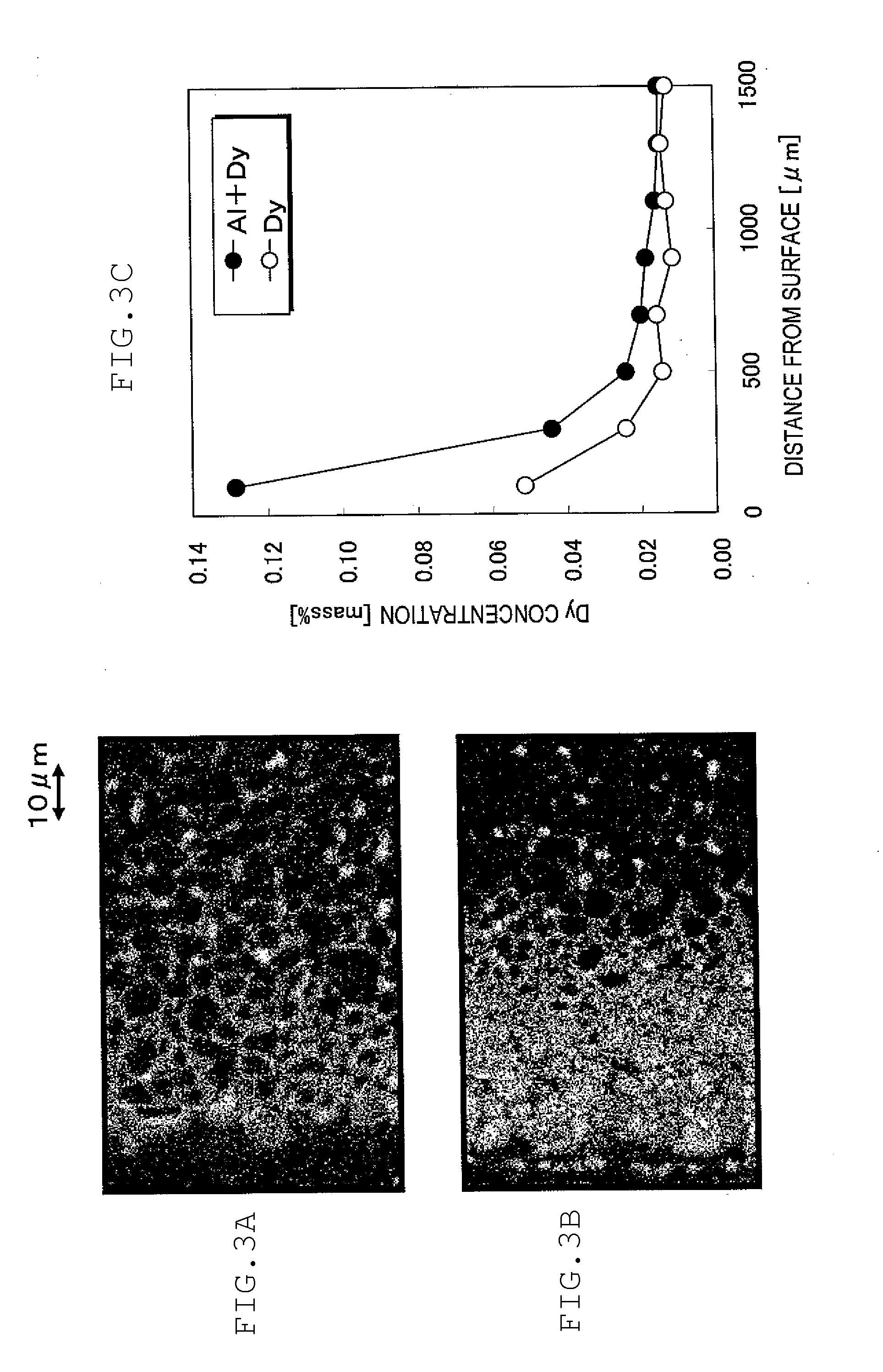
[0087]First, as in the first specific example described above, a number of sintered magnet bodies with a thickness of about 8 mm, a length of about 10 mm and a width of about 10 mm were made. Compared to the first through sixth examples described above, the sintered magnet bodies of this seventh specific example of a preferred embodiment of the present invention had a greater thickness of about 8 mm.
[0088]Next, a metal layer was deposited on the surface of these sintered magnet bodies using an electron beam evaporation system. Specifically, the following process steps were carried out.
[0089]First, the deposition chamber of the electron beam evaporation system was evacuated to reduce its pressure to about 5×10⁻³ Pa, and then was supplied with high-purity Ar gas with its pressure maintained at about 0.2 Pa. Next, a DC voltage of about 0.3 kV was applied between the electrodes of the deposition chamber, thereby performing an ion bombardment process on the surface of the sintered magnet...
PUM
| Property | Measurement | Unit |
|---|---|---|
| beam diameter φ | aaaaa | aaaaa |
| size | aaaaa | aaaaa |
| sizes | aaaaa | aaaaa |
Abstract
Description
Claims
Application Information