Distributed multiband antenna and methods

a multi-band antenna and antenna technology, applied in the field of antennas, can solve the problems of increasing complexity and cost, reducing the performance of the above-mentioned phantom head and hand, and narrow bandwidth of the pifa for wireless commercial applications, and achieving the effect of reducing the size of the exterior housing

Active Publication Date: 2011-10-27
CANTOR FITZGERALD SECURITIES
View PDF6 Cites 84 Cited by
  • Summary
  • Abstract
  • Description
  • Claims
  • Application Information

AI Technical Summary

Benefits of technology

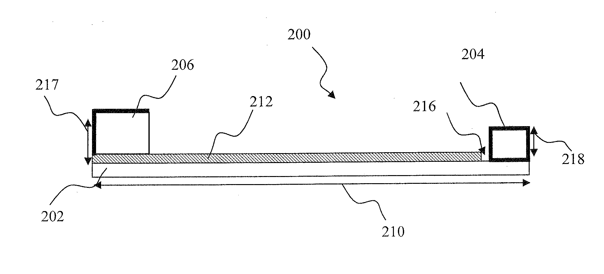
[0025]In another embodiment, the mobile device comprises a reduced-size mobile radio device operable in a lower and an upper frequency bands. The device comprises an exterior housing and a multiband antenna assembly, the antenna assembly comprising a rectangular ground plane having first and second substantially opposing regions. The mobile radio device being configured according to the method comprising: placing a first antenna element configured to resonate in the upper frequency band proximate to a the first region; and placing a second antenna element configured to resonate in the lower frequency band proximate to the second region. The first antenna element comprises a planar inverted-F antenna (PIFA); and the act of placing the first antenna element effects reduction of the ext...

Problems solved by technology

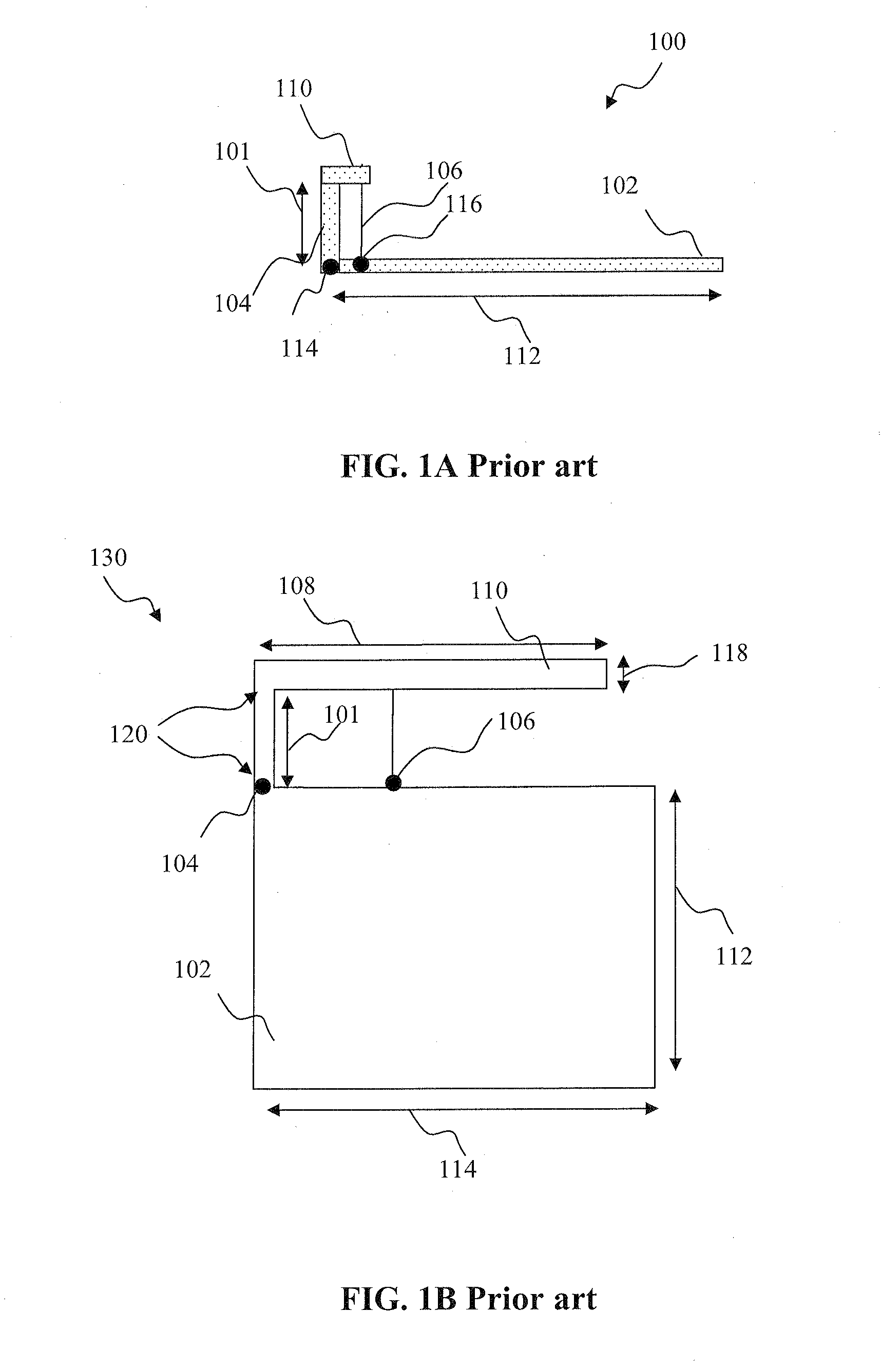
However, this requires the use of capacitive loading to compensate for the reactive component of the impedance that arises due to the shortened antenna structure.
One of the substantial limitations of PIFA for wireless commercial applications is its narrow bandwidth.
This approach inherently has drawbacks, as PIFAs require larger size (height in particular), and hence occupy a large volume to reach the desired lower frequency of multiband operation.
While monopole antennas typically perform well in the free...

Method used


Image

  • Distributed multiband antenna and methods
  • Distributed multiband antenna and methods
  • Distributed multiband antenna and methods

Examples


Embodiment Construction

[0048]Reference is now made to the drawings wherein like numerals refer to like parts throughout.

[0049]The terms “antenna,”“antenna system,” and “multi-band antenna” refer without limitation to any system that incorporates a single element, multiple elements, or one or more arrays of elements that receive / transmit and / or propagate one or more frequency bands of electromagnetic radiation. The radiation may be of numerous types, e.g., microwave, millimeter wave, radio frequency, digital modulated, analog, analog / digital encoded, digitally encoded millimeter wave energy, or the like. The energy may be transmitted from location to another location, using, or more repeater links, and one or more locations may be mobile, stationary, or fixed to a location on earth such as a base station.

[0050]As used herein, the terms “board” and “substrate” refer generally and without limitation to any substantially planar or curved surface or component upon which other components can be disposed. For ex...


PUM


Abstract

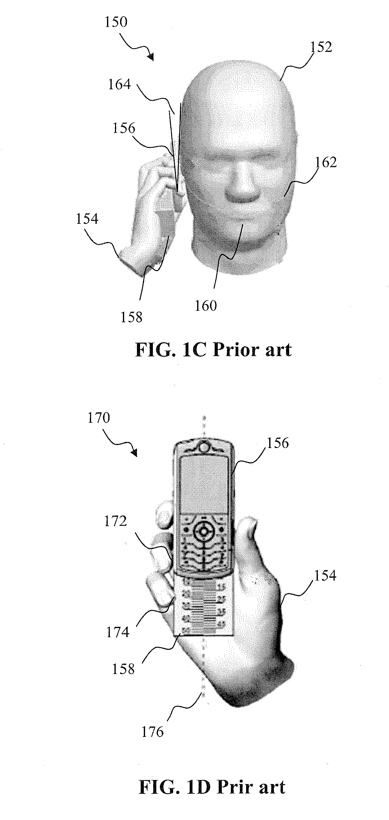
A distributed multiband antenna intended for radio devices, and methods for designing manufacturing the same. In one embodiment, a planar inverted-F antenna (PIFA) configured to operate in a high-frequency band, and a matched monopole configured to operate in a low-frequency band, are used within a handheld mobile device (e.g., cellular telephone). The two antennas are placed on substantially opposing regions of the portable device. The use of a separate low-frequency antenna element facilitates frequency-specific antenna matching, and therefore improves the overall performance of the multiband antenna. The use of high-band PIFA reduces antenna volume, and enables a smaller device housing structure while also reducing signal losses in the high frequency band. These attributes also advantageously facilitate compliance with specific absorption rate (SAR) tests; e.g., in the immediate proximity of hand and head “phantoms” as mandated under CTIA regulations. Matching of the low-frequency band monopole antenna is further described.

Description

COPYRIGHT[0001]A portion of the disclosure of this patent document contains material that is subject to copyright protection. The copyright owner has no objection to the facsimile reproduction by anyone of the patent document or the patent disclosure, as it appears in the Patent and Trademark Office patent files or records, but otherwise reserves all copyright rights whatsoever.1. FIELD OF THE INVENTION[0002]The present invention relates generally to antennas for use in wireless or portable radio devices, and more particularly in one exemplary aspect to a spatially distributed multiband antenna, and methods of utilizing the same.2. DESCRIPTION OF RELATED TECHNOLOGY[0003]Internal antennas are an element found in most modern radio devices, such as mobile computers, mobile phones, Blackberry® devices, smartphones, personal digital assistants (PDAs), or other personal communication devices (PCD). Typically, these antennas comprise a planar radiating plane and a ground plane parallel the...

Claims


Application Information

Patent Timeline
IPC IPC(8): H01Q21/30H01Q5/357H01Q5/378
CPCH01Q1/243H01Q9/0421H01Q5/378H01Q21/30H01Q5/357H01Q9/42
Inventor KORVA, HEIKKIANNAMAA, PETTERIRAAPPANA, ARI
Owner CANTOR FITZGERALD SECURITIES
Why Eureka
Try Eureka