Eureka AIR delivers breakthrough ideas for toughest innovation challenges, trusted by R&D personnel around the world.

Display data obtaining apparatus and display data obtaining method

a technology for obtaining apparatus and display data, which is applied in the direction of applications, ultrasonic/sonic/infrasonic diagnostics, instruments, etc., can solve the problem of deteriorating quantitative accuracy of obtained information, difficult to measure an acoustic wave in various positions around the entire subject, and insufficient amount of information to obtain inner information of a living body, etc. problem, to achieve the effect of reducing the fluctuation of sensitivity

Active Publication Date: 2011-10-27
CANON KK
View PDF3 Cites 9 Cited by
  • Summary
  • Abstract
  • Description
  • Claims
  • Application Information

AI Technical Summary

Benefits of technology

[0007]The present invention has been made based on the problem as described above. An object of the present invention is to provide a display data obtaining and diagnosis apparatus capable of reducing a fluctuation in sensitivity (spatial sensitivity distribution) for each location in a measurement object even in a limited measurement condition in which a photoacoustic wave generated in the entire subject cannot be obtained in a sufficient range.
[0009]According to the display data obtaining apparatus of the present invention, the fluctuation in sensitivity (spatial sensitivity distribution) which depends on location in the measurement object may be reduced even in the limited measurement condition in which the photoacoustic wave generated in the entire subject cannot be obtained in the sufficient range.

Problems solved by technology

There has been known a problem in that, the photoacoustic tomography apparatus causes a spatial sensitivity distribution specific to the apparatus, when an acoustic wave measurement region is insufficient compared to an information acquisition region, for example, when the acoustic wave may be received from not in all directions of a subject but in only a specific direction (“128-channel laser optoacoustic imaging system (LOIS-128) for breast cancer diagnostics”, Sergey A. Ermilov, Andre Conjusteau, Ketan Mehta, Ron Lacewell, P. Mark Henrichs, and Alexander A. Oraevsky, Proceedings of SPIE, Vol. 6086, 608609, 2006).
As a result, the quantitativity of obtained information is deteriorated.
However, when a large object, for example, breasts of a human are subjected to examination, it is difficult to measure an acoustic wave in various positions around the entire subject, and hence inner information of a living body cannot be obtained by using a sufficient amount of information.
In other words, when such objects are subjected to examination, the method of Xu et al. is not necessarily practical to eliminate the deterioration of the quantitativity of the obtained information.

Method used


Image

  • Display data obtaining apparatus and display data obtaining method
  • Display data obtaining apparatus and display data obtaining method
  • Display data obtaining apparatus and display data obtaining method

Examples


example 1

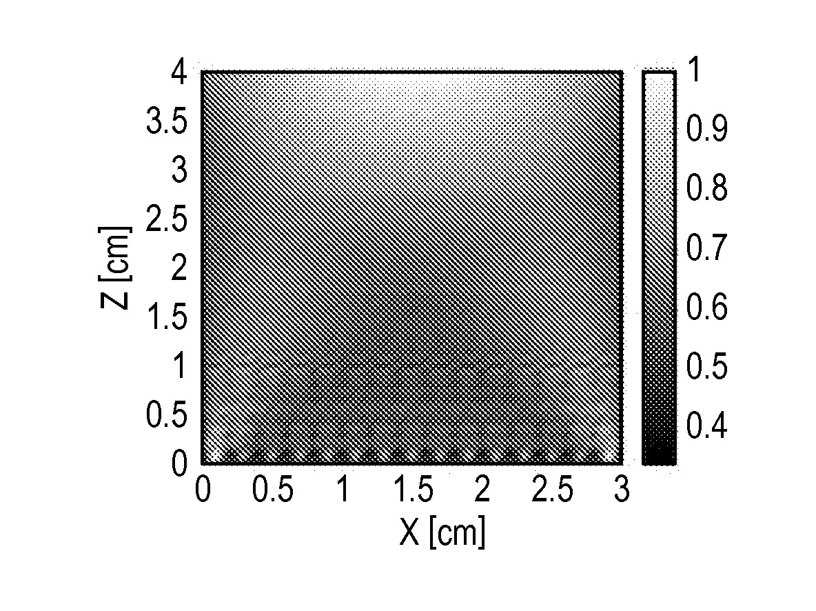
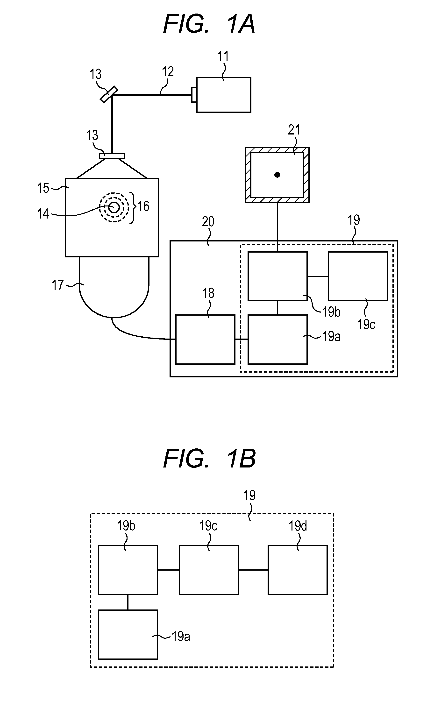
[0071]An example of the display data obtaining apparatus using a photoacoustic tomography, to which the embodiment of the present invention is applied, is described. The display data obtaining apparatus is described with reference to the schematic diagrams of FIGS. 1A and 1B. In this example, a Q-switch YAG laser for generating pulsed light of approximately 10 nanoseconds at a wavelength of 1,064 nm was used as the light source 11. The energy of the pulsed light generated from the laser is 0.6 J. The optical system 13 including a mirror and a beam expander was set so that the pulsed light was expanded to a radius of approximately 2 cm by the optical system 13 to irradiate the subject opposed to the acoustic wave probe 17 with the pulsed light. A rectangular phantom simulating a living body as illustrated in FIG. 4A was used as the subject 15. The used phantom was obtained by solidifying water with agar. The phantom was 5 cm in width, 5 cm in height, and 4 cm in depth. As illustrated...

example 2

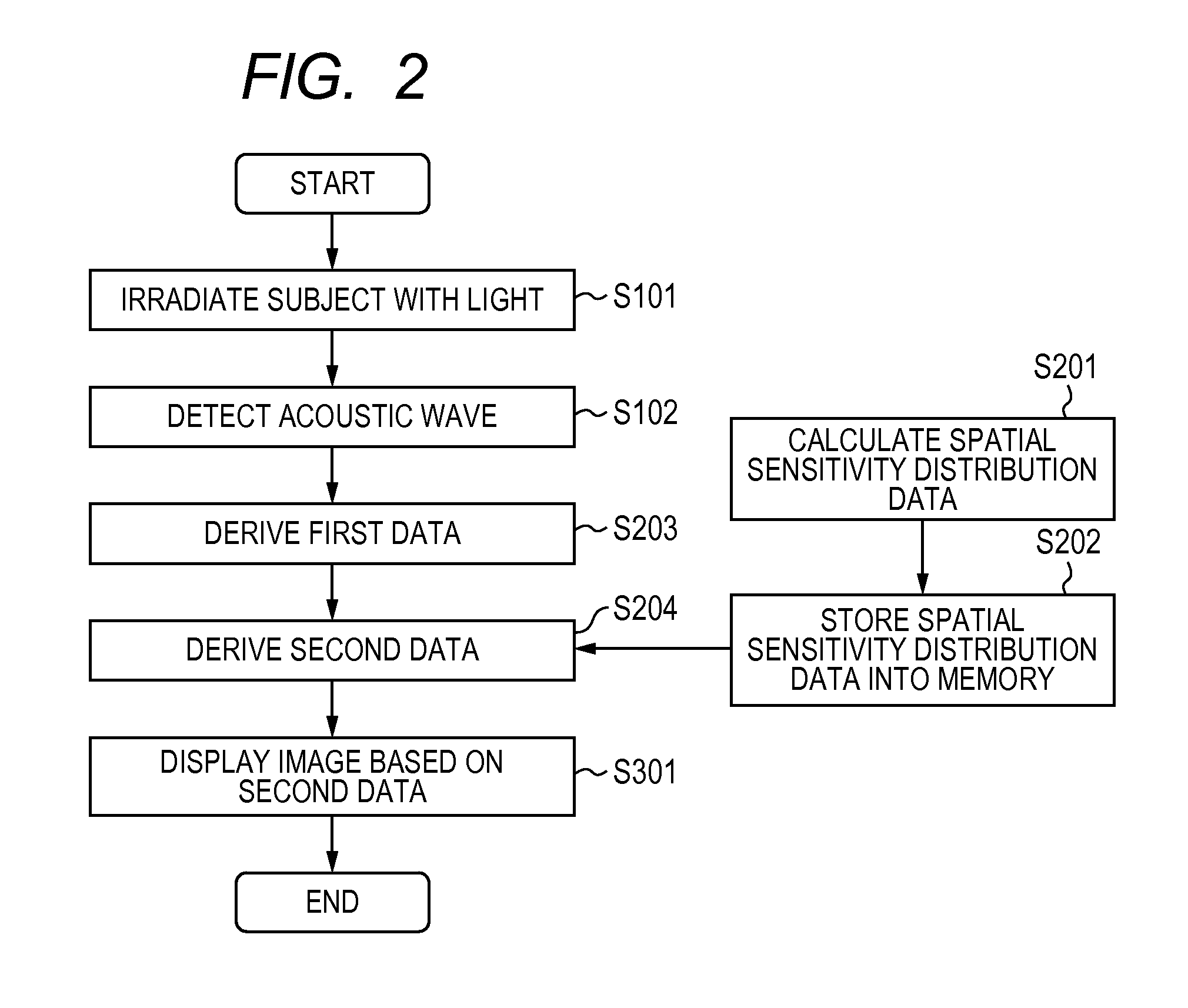
[0076]An example of the display data obtaining apparatus using the photoacoustic tomography, to which the embodiment of the present invention is applied, is described. In this example, the same phantom and measurement system as in Example 1 were used. Note that, the first data deriving method and the configuration of the apparatus are known. Therefore, the spatial sensitivity distribution data was calculated in advance by a workstation as a calculation unit prepared separately from the display data obtaining apparatus. After that, the spatial sensitivity distribution data was stored in a hard disk of another workstation as the display data obtaining unit 19 of the display data obtaining apparatus. Note that, the spatial sensitivity distribution data was calculated by substantially the same method as in Example 1.

[0077]Next, the phantom is irradiated with light as in Example 1. Obtained digital data was transferred to the workstation (WS) as the signal processing unit 20 and stored i...

example 3

[0079]An example of the display data obtaining apparatus using the photoacoustic tomography, to which the embodiment of the present invention is applied, is described. In this example, the same phantom and measurement system as in Example 1 were used. First, before the measurement of the phantom, a very-small optical absorber in which ink entered a tip end of a transparent glass tube was irradiated with light and acoustic waves were received. Received signals were used to calculate a voxel value in the same position as the very-small sound source. Such an operation was repeated in various positions to experimentally obtain spatial sensitivity distribution data. The spatial sensitivity distribution data was stored in the memory 19c of the signal processing unit 20. Next, the phantom is irradiated with light as in Example 1. Obtained digital data was transferred to the workstation (WS) as the signal processing unit 20 and stored in the WS. Then, the first data exhibiting the absorptio...


PUM


Abstract

Provided is a display data obtaining apparatus capable of, in photoacoustic tomography, reducing a fluctuation in sensitivity which depends on location for image reconstruction even in a limited measurement condition in which a photoacoustic wave generated in the entire subject cannot be obtained in a sufficient range. The display data obtaining apparatus includes: an acoustic wave detecting unit for detecting an acoustic wave generated from a subject irradiated with pulsed light to obtain a signal; a first data deriving unit for deriving first data exhibiting an optical characteristic distribution of the subject based on the obtained signal obtained by the acoustic wave detecting unit; a memory for storing spatial sensitivity distribution data specific to the display data obtaining apparatus; and a second data deriving unit for deriving second data exhibiting the optical characteristic distribution of the subject using the first data and the spatial sensitivity distribution data.

Description

BACKGROUND OF THE INVENTION[0001]1. Field of the Invention[0002]The present invention relates to a display data obtaining apparatus and a display data obtaining method with which a signal of an acoustic wave from an inner portion of a subject to be examined (hereinafter, referred to as “subject”) irradiated with light is detected, and the detected signal is processed to obtain information of the inner portion of the subject.[0003]2. Description of the Related Art[0004]In medical fields, there has been actively developed an optical imaging apparatus for irradiating a living body with light emitted from a light source such as a laser, and for displaying on a display information of an inner portion of the living body which is obtained based on light entering the living body. An example of the optical imaging technology is photoacoustic tomography (PAT). In the photoacoustic tomography, a living body is irradiated with pulsed light from the light source so as to detect an acoustic wave ...

Claims


Application Information

Patent Timeline
IPC IPC(8): G06T11/20
CPCA61B5/0073A61B8/00A61B5/0095A61B8/0825
Inventor FUKUTANI, KAZUHIKO
Owner CANON KK
Why Eureka
Eureka Blog
Learn More