
Toner containing metallic flakes and method of forming metallic image

Active Publication Date: 2011-10-27
EASTMAN KODAK CO
View PDF6 Cites 57 Cited by
  • Summary
  • Abstract
  • Description
  • Claims
  • Application Information

AI Technical Summary

Benefits of technology

[0010]It is an object of the present invention to provide toner polymeric particles that may contain high concentrations of encapsulated metallic flakes.
[0011]It is further an object of the present invention to provide porous toner particles that contain encapsulated metallic flakes that can effectively produce metallic hue by a printing processes such as electrophotography or electrography upon fusing of the toner particles to a receiver substrate.
[0013]It is a further object of the present invention to provide a scalable and efficient process for the production of the above toner particles.
[0014]It is a further object of the invention to provide a method for producing an electrophotographic toner image with enhanced metallic hue and luster or sheen effect.
[0015]It is still another object of the present invention to directly utilize commercial metallic flakes in such particles and methods so that further surface modifications are not needed.
[0019]In another embodiment, the invention is directed towards a method for forming a toner image comprising: forming a toner image on a substrate, wherein the toner image comprises toner particles according to the invention comprising porous toner particles having metallic flakes encapsulated therein; and fixing the toner particles to the substrate by application of heat to fuse the toner particles to the substrate, wherein pores within the toner particles provide space for the metallic flakes to re-orient within the toner particle binder phase to be relatively more parallel with the receiver substrate surface upon fusing. The porous structure of the toner particle further enables use of a lower amount of binder compared to solid particles, enabling thinner fused images, further enhancing alignment of the metallic flakes with the substrate surface upon fusing.

Problems solved by technology

This could impair transfer and development as the applied electrostatic force used to urge the marking particles towards the primary imaging member or to or from a receiver member would vary with the charge on the marking particles.
Moreover, even if the charge did not reverse sign or become so significantly altered so as to prevent development or transfer, the control of either or both of these operations could be impeded, resulting in incorrect amounts of marking particles being deposited, with corresponding undesirable density variations and other artifacts occurring.
An immense problem here is posed in particular by the reproduction of metallic hues.
A gold tone is particularly difficult to reproduce by means of such a color mixture.
But in the case of electrophotographic toners, where magnetic and / or electrical and especially electrostatic properties are decisive, this is particularly problematic, since metallic constituents may have an adverse effect on these properties.
But the appearance of prints in particular may be adversely affected by chemical reactions of the metallic constituents due to the halides, which can promote oxidations of the constituents for example.
For instance, the tarnishing with which everyone is familiar from copper or silver objects may occur, making the metallic quality unattractive or disappear completely.
Moreover, these toners are only lightly metallically colored, which is insufficient to reproduce a gold tone in printed matter.
This random orientation leads to the loss of metallic hue, and causes a rather dark appearance when such toners are fixed to a receiver sheet using heated fusing rollers.
However, the toner was not shown to contain encapsulated metallic flakes in the polymeric resin.
Thus, there is a possibility that the metallic pigment itself may be detached from the polymer during the particle making process, resulting in inhomogeneities in the toner that can cause transfer and cleaning problems.

Method used


Image

  • Toner containing metallic flakes and method of forming metallic image

Examples


example 1

Invention

Porous Toner Containing Aluminum Flakes

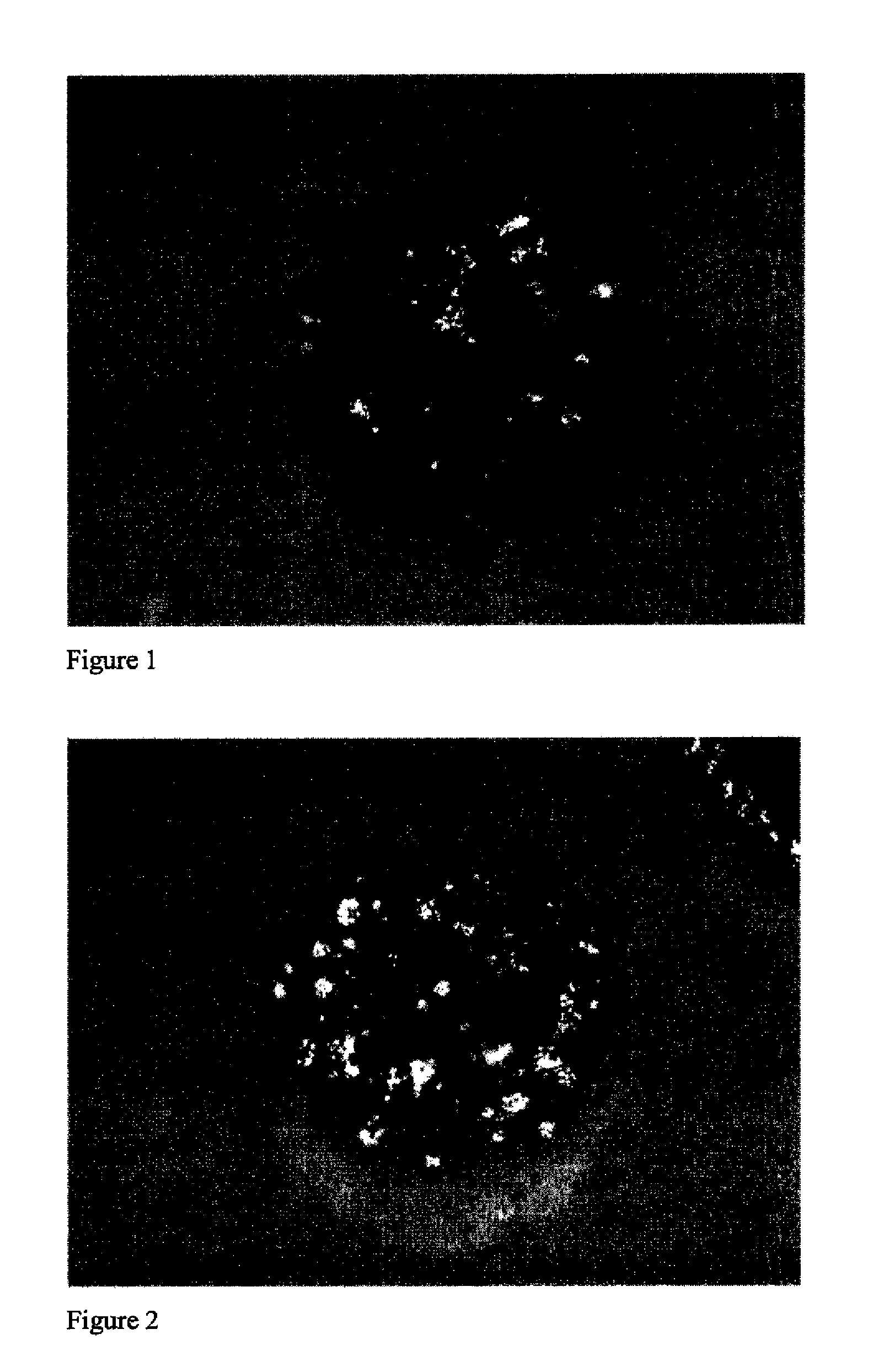
[0060]A multiple emulsion process in conjunction with an evaporative limited coalescence (ELC) process as described above was used to prepare the porous toner of this example. A first water phase (W1) was prepared using 37.5 g of a 4 wt % carboxymethyl cellulose solution in water along with 34.6 grams of water, and a premixed paste of 2.5 grams OBRON SF 121 Aluminum flakes and 5 grams SYNFAC 8337. The oil phase was made up using 141.7 g of 29.6% solution of Kao N resin in ethyl acetate, 16.4 grams of a dispersion of 24.4% WE-3 wax in ethyl acetate containing 20 wt % P2000 dispersant based on wax, 0.75 grams of a charge control agent FCA 2508N and 88.5 g ethyl acetate. To this oil phase was added the W1 phase followed by mixing with a Silverson L4R Mixer fitted with a large holed disintegrating head. A part (326 g) of the resulting water-in-oil (W1 / O) emulsion was gently stirred into 544 grams of a water phase (W2) comprising 10.4 grams...

example 2

Comparative

Solid Toner Containing Aluminum Flakes

[0061]Kao N resin was dissolved in ethyl acetate and was added as a 29.6% solution to a premixed paste of 2.5 grams OBRON SF 121 Aluminum flakes and 5 grams SYNFAC 8337. To this was added and mixed in 16.4 grams of a dispersion of 24.4% WE-3 wax in ethyl acetate containing 20 wt % P2000 dispersant based on wax followed by 0.75 grams of a charge control agent FCA 2508N. This resulting oil phase was dispersed in 534 grams of a pH 4 citrate / phosphate buffer comprising 10.5 grams of NALCO 1060 followed by magnetic stirring. The ethyl acetate was evaporated using a Buchi ROTA VAPOR RE120 at 30° C. under reduced pressure to yield solid particles of Kao N containing metal flakes. The silica on the surface of the toner was removed by stirring for 15 min at pH12.5 using potassium hydroxide. The particles were then washed and dried. The median particle size measured using the Horiba LA-920 was 67 micrometers.

Fusing

[0062]Solid vs. Porous Toners...


PUM


Abstract

The present invention relates to a porous toner particle with encapsulated metallic flakes. The porous particle containing metallic flakes can be useful for reproduction of a metallic hue upon fusing to a substrate, preferably golden or silvery hue, and for manufacturing of printed circuits, by a printing process, especially electrophotography.

Description

FIELD OF THE INVENTION[0001]This invention relates to electrostatographic toners, more particularly to porous toner particles with encapsulated metallic flakes for use in the reproduction of printed images having metallic hues, and for production of printing circuit boards, by a printing process such as electrophotography.BACKGROUND OF THE INVENTION[0002]Electrophotographic images are typically produced by first uniformly charging a primary imaging member such as a photoconducting web or drum using known means such as a corona or roller charger. An electrostatic latent image is then formed by image-wise exposing the primary imaging member using known means such as optical exposure, laser scanners, or LED arrays. The electrostatic latent image is then rendered into a visible image by bringing the electrostatic latent image into close proximity to marking particles, alternatively referred to as toner particles, which have been electrically charged so that they will be attracted to the...

Claims


Application Information

Patent Timeline
IPC IPC(8): G03G9/093G03G13/20G03G5/00
CPCG03G9/0804G03G9/0821G03G9/0823G03G9/09708G03G9/0827G03G9/0902G03G9/0926G03G9/0825
Inventor NAIR, MRIDULAYANG, XIQIANGSEDITA, JOSEPH S.
Owner EASTMAN KODAK CO
Learn More