
System for Non-Contrast Enhanced MR Anatomical Imaging

a technology of enhanced mr and anatomical imaging, applied in the field of system for enhanced mr (magnetic resonance) imaging, can solve the problems of time-consuming and operator dependent, and achieve the effects of enhancing arterial blood flow, accelerating 3d image volume acquisition, and enhancing mr imaging

Active Publication Date: 2011-10-27
SIEMENS MEDICAL SOLUTIONS USA INC
View PDF1 Cites 11 Cited by
  • Summary
  • Abstract
  • Description
  • Claims
  • Application Information

AI Technical Summary

Benefits of technology

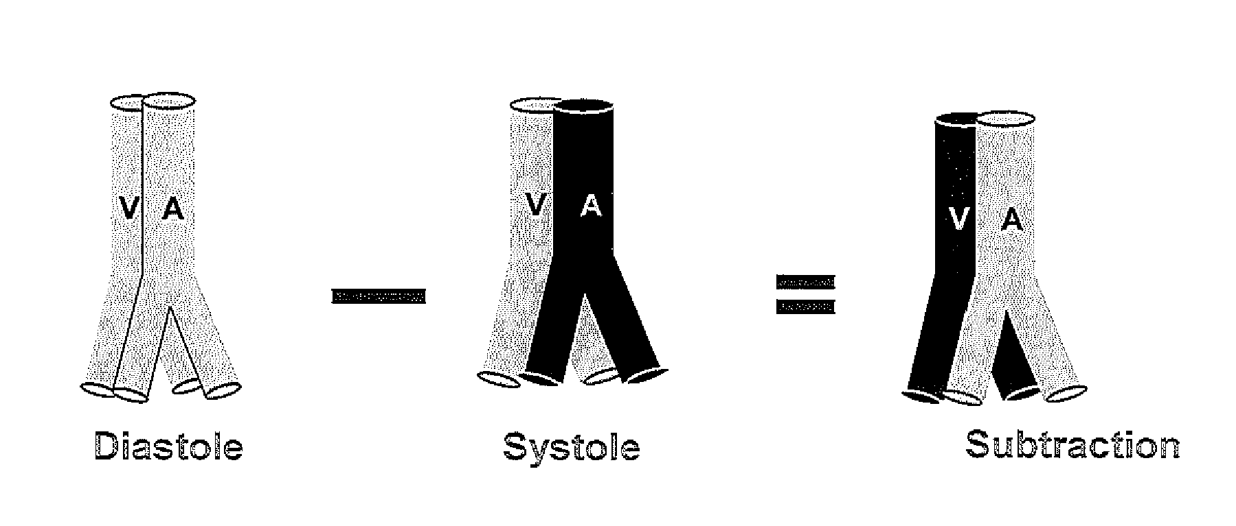
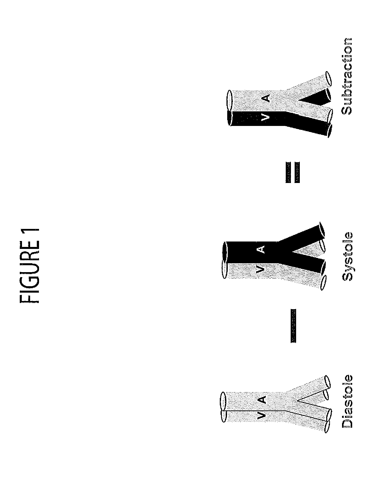
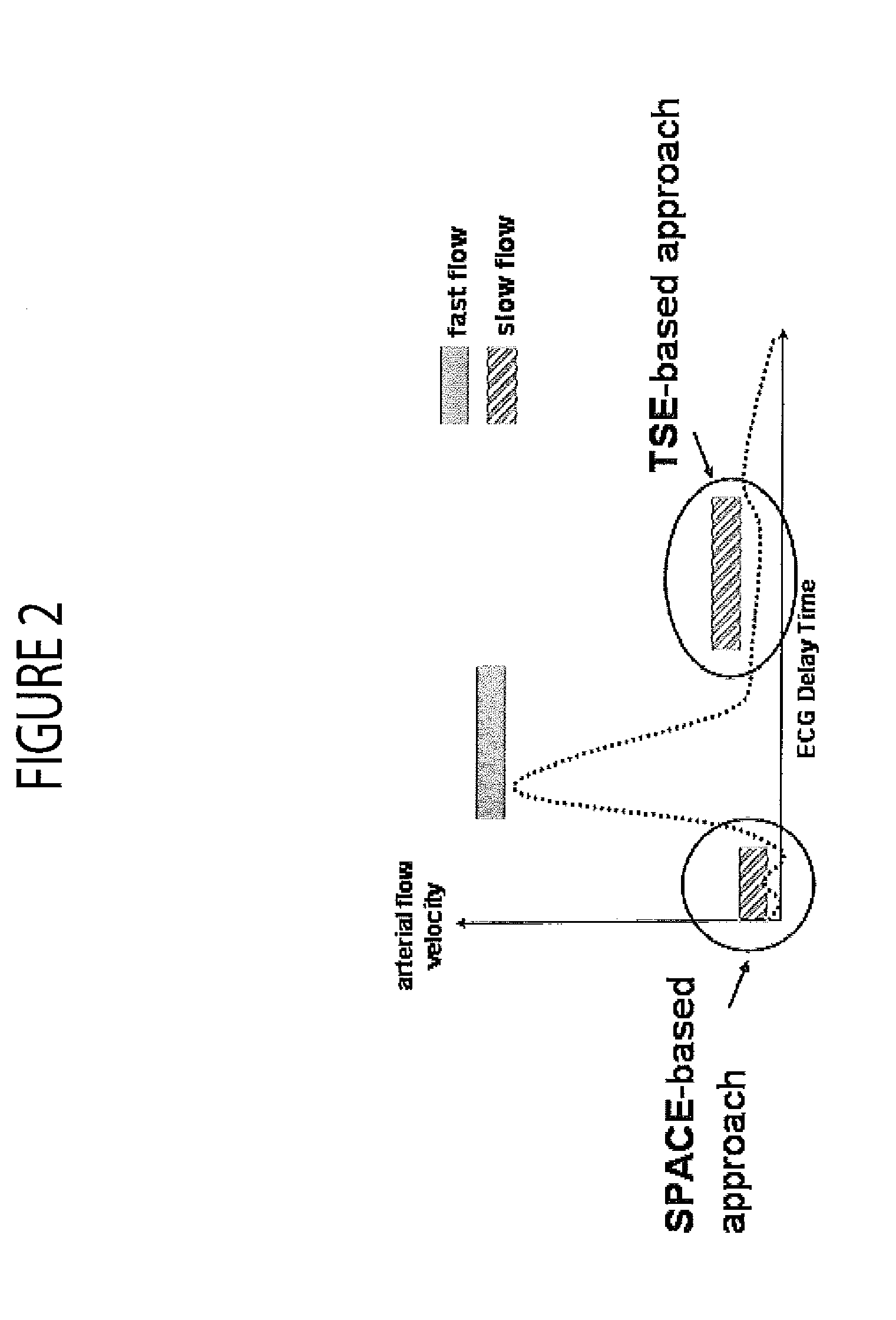
[0006]A system provides user friendly MR device operation with ECG triggering and Spin Echo sequence based Non Contrast Enhanced MR Angiography using transversal orientation acquisition and continuous patient table or electronic FOV movement to accelerate 3D image volume acquisition. A system for Non-Contrast Agent enhanced MR imaging, includes an MR image acquisition device. The MR image acquisition device acquires over multiple heart cycles, first and second datasets representing first and second image slabs individually comprising multiple image slices oriented substantially perpendicular in at least one axis to direction of vasculature blood flow, in response to a heart cycle synchronization signal. Within an individual heart cycle, a slice of a first image slab and a slice of a second image slab are acquired with one slice of one slab being acquired at a relatively fast blood flow portion of the heart cycle and the other slice of the other slab being acquired at a relatively slow blood flow portion of the heart cycle. An image data processor processes imaging datasets representing the first and second image slabs to provide first and second volume datasets representing a 3D volume imaged at the fast blood flow portion and the slow blood flow portion respectively and for providing a difference dataset representing an image difference between the first and second volume datasets and enhancing arterial blood flow. A display processor provides data representing an image showing the enhanced arterial blood flow.

Problems solved by technology

Further, in order to achieve a larger field of view (FOV) coverage, known MR systems typically use a coronal orientation together with a localization scan to find vessels prior to an MRA scan which is time-consuming and operator dependent.

Method used


Image

  • System for Non-Contrast Enhanced MR Anatomical Imaging
  • System for Non-Contrast Enhanced MR Anatomical Imaging
  • System for Non-Contrast Enhanced MR Anatomical Imaging

Examples


Embodiment Construction

Definitions

[0019]An inversion recovery (IR) pulse inverts longitudinal magnetization from the positive z-axis by 180 degrees to the negative z-axis. IR pulses are used as preparation pulses prior to a main imaging pulse sequence to achieve different kinds of MR contrast (such as T1 weighted, T2 weighted). Adiabatic IR pulses are used to give more uniform contrast throughout an imaging volume than non-adiabatic RF pulses.

[0020]iPAT (integrated Parallel Acquisition Techniques) comprises “parallel imaging”. It enables faster scanning through reduced phase encoding and addition of RF coil information. An iPAT factor of 2 enables scanning about twice as fast, iPAT factor of 3 enables scanning about three times as fast and so on.

TI=inversion time, the time between an inversion recovery pulse and the next RF excitation pulse. TI determines the image contrast.

T1=the longitudinal (or spin-lattice) relaxation time T1 decay constant.

T2=the transverse (or spin-spin) relaxation time T2 is the de...


PUM


Abstract

A system for Non-Contrast Agent enhanced MR imaging, includes an MR image acquisition device that acquires first and second datasets representing first and second image slabs individually comprising multiple image slices acquired at fast and slow blood flow portions of a heart cycle and oriented substantially perpendicular in at least one axis to direction of vasculature blood flow, in response to a heart cycle synchronization signal. An image data processor processes imaging datasets representing the first and second image slabs to provide first and second volume datasets representing a 3D volume imaged at the fast blood flow portion and the slow blood flow portion respectively and for providing a difference dataset representing an image difference between the first and second volume datasets and enhancing arterial blood flow. A display processor provides data representing an image showing the enhanced arterial blood flow.

Description

[0001]This is a non-provisional application of provisional application Ser. No. 61 / 326,679 filed 22 Apr. 2010 and Ser. No. 61 / 326,677 filed 22 Apr. 2010 by J. Xu.FIELD OF THE INVENTION[0002]This invention concerns a system for Non-Contrast Agent enhanced MR (magnetic resonance) imaging, by acquiring image slices oriented substantially perpendicular to direction of vasculature blood flow, at a relatively fast blood flow portion of a heart cycle and at a relatively slow blood flow portion of the heart cycle and by determining a difference between the slices.BACKGROUND OF THE INVENTION[0003]Known systems employ ECG-gated (Turbo) spin echo (TSE) imaging for MR Angiography using an intrinsic contrast mechanism by exploiting differences in the velocity of arterial blood during a cardiac cycle. In this type of imaging, an MR signal from stationary tissue and non-pulsatile venous blood is canceled by image subtraction, while an MR signal from arterial blood is preserved. This is because, fa...

Claims


Application Information

Patent Timeline
Patent Type & Authority Applications(United States)
IPC IPC(8): A61B5/055
CPCA61B5/0402A61B5/055G01R33/4822G01R33/5673G01R33/4835G01R33/5617G01R33/5635G01R33/4833A61B5/318
Inventor XU, JIAN
Owner SIEMENS MEDICAL SOLUTIONS USA INC
Learn More