Ammonia burning internal combustion engine

Inactive Publication Date: 2011-11-03
TOYOTA JIDOSHA KK
View PDF2 Cites 18 Cited by
  • Summary
  • Abstract
  • Description
  • Claims
  • Application Information

AI Technical Summary

Benefits of technology

[0007]When using a plasma jet ignition plug which emits a plasma jet, the surface area of the spark flame nucleus becomes larger, so the ammonia is made to easily burn, while when using a plurality of spark plugs which generate sparks, ignition flame nuclei are generated at a plurality of locations, so the ammonia is made to easily burn.

Problems solved by technology

However, in this case, burning such fuels produces CO2, which causes global warming.
On the other hand, burning ammonia does not produce CO2 at all.
However, ammonia is harder to burn compared with fossil fuels.

Method used


Image

  • Ammonia burning internal combustion engine
  • Ammonia burning internal combustion engine
  • Ammonia burning internal combustion engine

Examples


Embodiment Construction

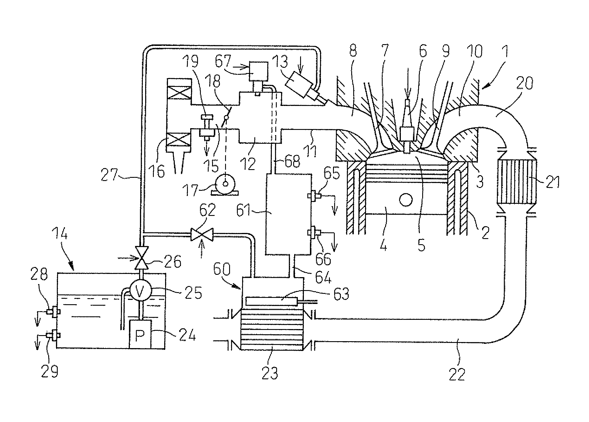
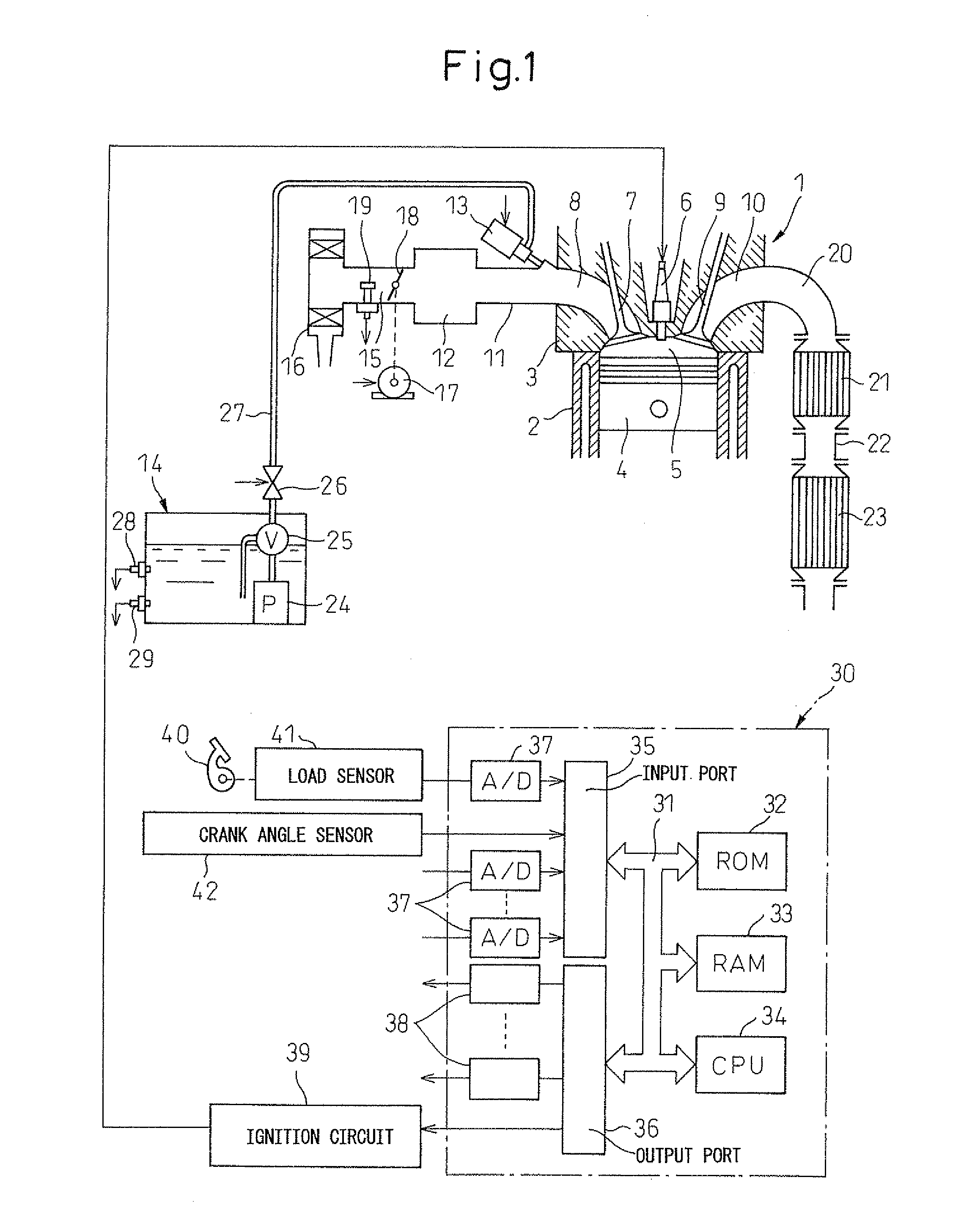
[0015]Referring to FIG. 1, 1 indicates an internal combustion engine body, 2 a cylinder block, 3 a cylinder head, 4 a piston, 5 a combustion chamber, 6 an ignition device which is arranged at the center of the top surface of the combustion chamber 5, 7 an intake valve, 8 an intake port, 9 an exhaust valve, and 10 an exhaust port. The intake port 8 is connected through an intake branch pipe 11 to a surge tank 12. In each intake branch pipe 11, a liquid ammonia injector 13 for injecting liquid ammonia toward the interior of each corresponding intake port 8 is arranged. This liquid ammonia injector 13 is fed with liquid ammonia from a fuel tank 14.

[0016]The surge tank 12 is connected through an intake duct 15 to an air cleaner 16. In the intake duct 15, a throttle valve 18 driven by an actuator 17 and an intake air amount detector 19 using for example a hot wire are arranged. On the other hand, the exhaust port 10 is connected through an exhaust manifold 20 to an ammonia adsorbent 21. ...


PUM


Abstract

An internal combustion engine in which ammonia which is fed into a combustion chamber is ignited by an ignition device which is arranged in the combustion chamber. As this ignition device, at least one plasma jet ignition plug which emits a plasma jet or a plurality of spark plugs which generate sparks are used.

Description

TECHNICAL FIELD[0001]The present invention relates to an ammonia burning internal combustion engine.BACKGROUND ART[0002]In an internal combustion engine, in the past, the fuel used has mainly been fossil fuels. However, in this case, burning such fuels produces CO2, which causes global warming. On the other hand, burning ammonia does not produce CO2 at all. Thus, there is known an internal combustion engine designed so as to use ammonia as fuel and not produce CO2 (for example, see Patent Literature 1).[0003]However, ammonia is harder to burn compared with fossil fuels. Therefore, when using ammonia as fuel, some sort of measure is required for making the ammonia easier to burn. Thus, in the above-mentioned internal combustion engine, exhaust heat is utilized to produce hydrogen from ammonia, the hydrogen produced from the ammonia is stored in a hydrogen storing alloy, the hydrogen produced from the ammonia or the hydrogen stored in the hydrogen storing alloy is fed into an auxiliar...

Claims


Application Information

Patent Timeline
IPC IPC(8): F02B43/10F02M37/00F01N3/10
CPCF01N3/2073Y02T10/36F02B43/10F02B2023/085F02M21/0206F02M21/0287F02P9/007F02P15/02Y02T10/32F02D19/0644F02M21/0275F02M21/0284F02M21/06F02D19/024F02D19/027F02M21/0278F01N2240/25Y02T10/30
Inventor KOJIMA, SUSUMUNAKAMURA, NORIHIKOSHIMIZU, RIOSUGIMOTO, TOMOJIROKIM, KYOUNG-OH
Owner TOYOTA JIDOSHA KK
Why Eureka
Try Eureka