However, no widely-used wing-in-ground effect craft still exists that could offer safety and / or cargo efficiency and / or ease of operation compared to those of conventional aircraft or ships, since no acceptable integral
engineering solution has been proposed to meet main challenges associated with operations of WIG craft, that is, longitudinal stability, seaworthiness and
amphibian properties, implemented in design combining ease of use and maintenance.
Besides, aerodynamic forces and moments affecting
pitch control feature somewhat complicated nature of dependence on flight parameters and, what is more important, they boast higher gradients of change.
Widely-used methods of providing longitudinal stability in tight time flight nearby water or ground surface minimizing decision-making interval may and, in fact, do cause crashes.
This is due to development of emergent conditions in fractions of seconds at external disturbances or in faulty control over craft.
The challenge is high risks in maneuvers involving
pitch angle variations at heights comparable to length of the aerial vehicle.
This is confirmed by both accidents with WIG craft and numerous
airplane crashes and emergencies that have occurred in take-off and landing.
On the one hand, it is limited by emergence of high
impact loads during take-off and landing in heavy sea conditions which may lead to damage and disruption of structure, and also to development of forces and moments that prevent the craft from reaching liftoff speed and disrupt hydrodynamic conditions that are necessary for safe completion of take-off or landing.
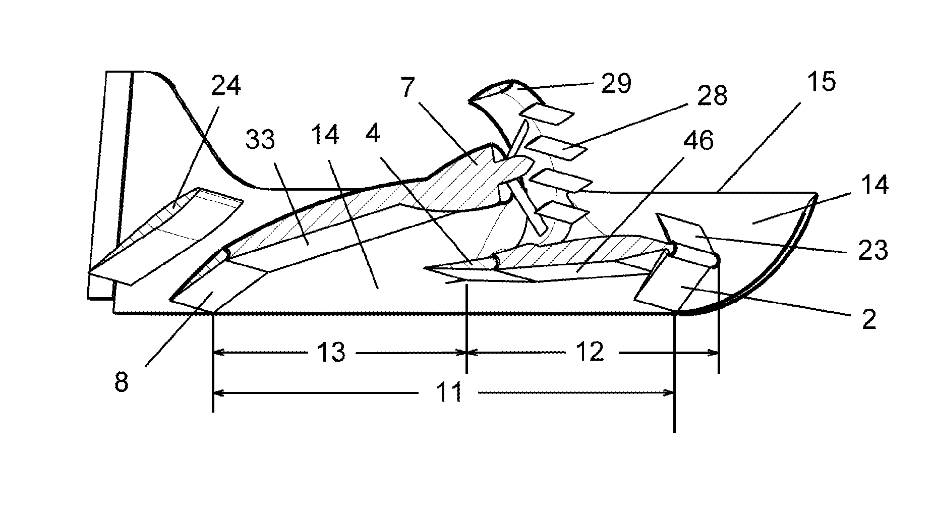
On the other hand, seaworthiness is limited by effective relative height of ground effect flight which depends on WIG craft geometry, that is, overall length and width of its airfoil (length of MAC).
Any change in magnitude of these forces is accompanied by progressing disturbance of previously established balance.
Therefore, in the longitudinal direction, the single-axis
carriage and aerodynamic configurations corresponding to it are unstable in principle.
But this type of WIG craft also has substantial disadvantageous features, i.e. necessity in take-off run,
fine tuning to a particular speed and height or
narrow range of variations thereof, very low
effective height of ground effect flight (in relation to overall length of the vehicle) which considerably limits seaworthiness.
Additionally, there is no amphibiousness at all or there is limited amphibiousness that requires slips with hard surface or shallow angles of ascent.
No capability of operating a flight outside ground effect zone or load
discharge through use of static
air cushion is provided.
For “single-axis” aerodynamic configurations, it is much more difficult to achieve self-stabilization (self-balancing for
pitch control) which makes the main problem about configurations of this type.
Airplane-type configuration with low-positioned wing and pressure boost, on which WIG craft KM, Orlyonok and Lun′ are based (FIG. 65, FIG. 54, FIG. 55 [2]), does not provide capability of restoring original balance of moments in relation to center of gravity after
impact of occasional disturbance factors, and this means progressing
instability of
pitch control.
As the craft leaves ground effect zone, center of pressure shifts forwards which leads to rapid decrease of dive moment due to lifting force with simultaneous uncontained growth of surplus pitch moment, which may result in WIG craft reaching a supercritical
angle of attack, loss of speed,
airflow breakdown and stall.
Application of advanced stabilizer with area comparable to main wing still failed to save some heavy WIG crafts from
crash.
Therefore, application of
airplane-type
layout in design of heavy and super-heavy wing-in-ground effect craft was a conceptual error, as R. Alekseyev himself admitted.
Seaworthiness is insufficient.
Airplane-type aerodynamic configuration of wing-in-ground effect craft has limited variability and is suitable only for limited applications, for example, for type A WIG craft: “Volga-2”—SU Patent 1786768, Aquaglide FIG. 70 [2].
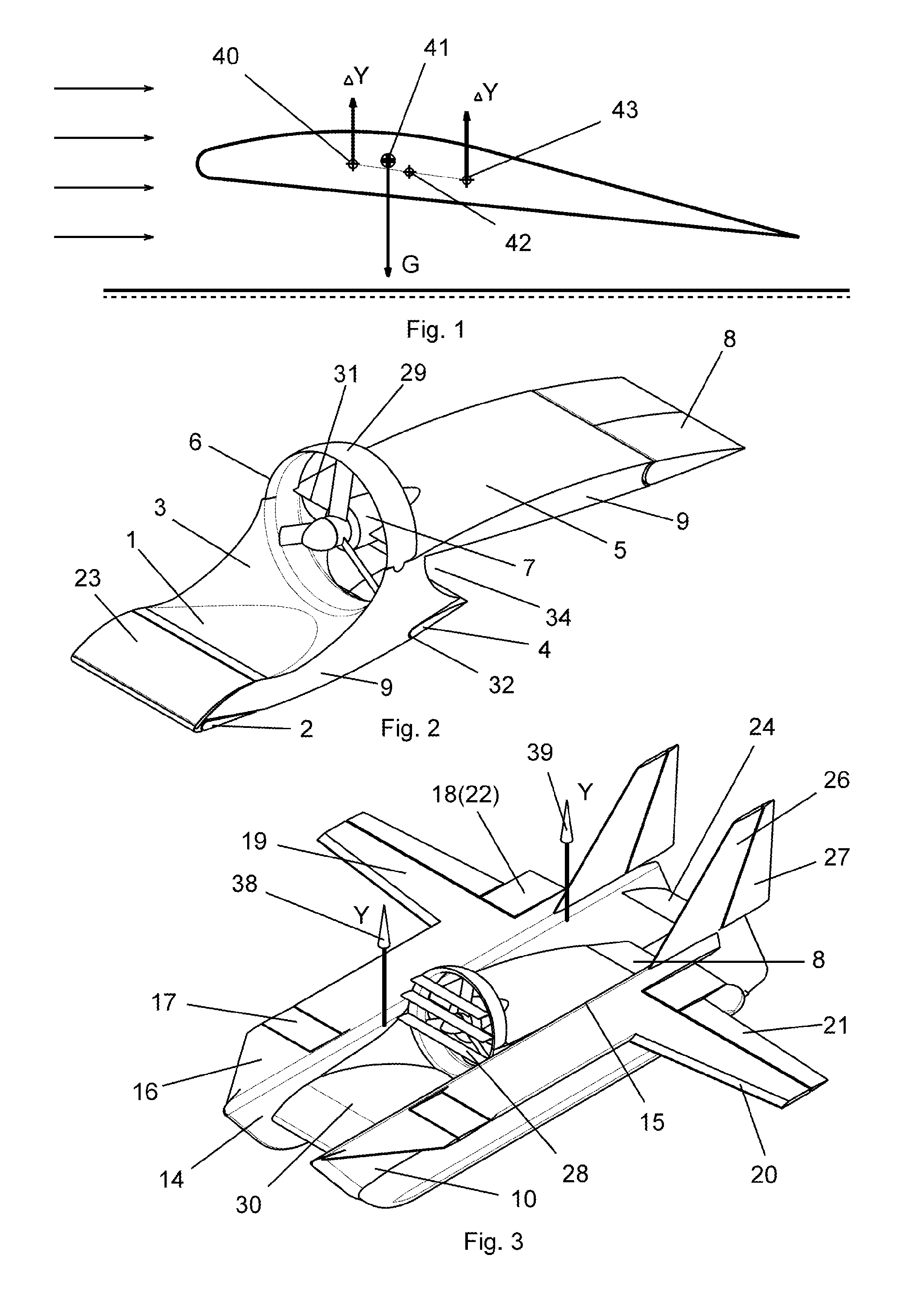
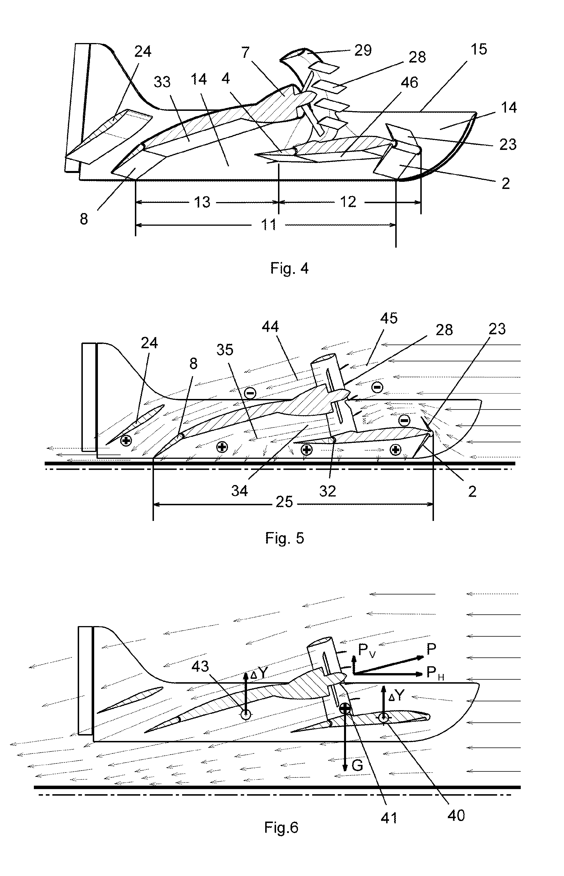
Their longitudinal stability is achieved through application of wing design with S-shaped aerofoil (with lower lifting performance) and precise positioning of center of gravity,
fine tuning to low ground effect
flight height, pulling propellers positioned ahead of the wing with pressure boost under the wing, lower
payload, limited
engine power and limited seaworthiness.
Airplane-type configuration by A. Lippisch also requires take-off run, is fine-tuned to ground effect
flight height, has insufficient stability during transitions and is unsafe during
free flight, unsuitable for high speeds, inconvenient in practical use and maintenance and is implemented with low specific loads on the wing.
It is not optimum for heavy craft.
It is difficult to meet static and dynamic
stability conditions in
airplane-type configurations with single wing because distance between the focuses is small compared to length of chord, therefore center of gravity should be precisely positioned within a
narrow range.
This, together with the need to adjust pitch, complicates piloting during transitions and in case of different disturbances.
There are known guidance materials on piloting wing-in-ground effect craft based on configuration by A. Lippisch that have been derived from computational modeling of WIG craft movement and accidents involving such vehicles [13], which show that it is insufficient to just meet conditions of static and dynamic stability for stabilized flight in order to ensure safety in transient
modes.
The “Flying Wing” configuration in the form of known attempted embodiments (including the U.S. Columbia project) is unstable.
It is required to either apply automated control and damping systems or limit flight performance or apply substantial stabilizing or additional load-carrying planes, but in this case such configuration becomes very close to “
Composite Wing” arrangement.
However, notwithstanding the fact that high-aspect outer wings do improve longitudinal stabilization, these aerodynamic WIG craft do not have stabilization ability characteristic of “two-axis” configuration, therefore in the case of strong
wind disturbance or piloting error they are not completely protected from abrupt pitching and leaving ground effect zone, with loss of speed and control.
Additionally, design under RU Patent 2099217 lacks passenger comfort and ease of maintenance.
In addition to lower
visibility, this causes mechanical damage to structure surfaces by sand and pebbles, thus necessitating additional protection for engine air filters.
In
cold climate, dry fresh
snow may be lifted in the air to lower
visibility down to several meters, which renders safe movement over ground impossible.
As to pressure boost under the wing, impulse from propulsive units with shrouded propellers is used irrationally and detrimental
pressure rise is caused on the upper
leading edge of the wing due to air
stream directed to surface at wide angles.
This necessitates application of sophisticated high-lift devices on wing
leading edge, which makes the structure too complex and heavy.
Even with pressure boost provisions this configuration still requires take-off run and landing roll.

