Apparatus And Methods For Gas Chromatography - Mass Spectrometry

a mass spectrometry and apparatus technology, applied in the field of apparatus and methods for mass spectrometry analysis of analyte materials, can solve the problems of inability to meet expectations, and insufficient sensitivity of the technique, so as to reduce the ionization volume, increase the concentration of analyte molecules, and increase the number of analyte ions generated

Active Publication Date: 2011-11-03
WATERS TECH CORP
View PDF4 Cites 41 Cited by
  • Summary
  • Abstract
  • Description
  • Claims
  • Application Information

AI Technical Summary

Benefits of technology

[0014]By directing the flow of second gas as described, the ionization volume is reduced from that which it would occupy in the absence of the second gas, thereby increasing the concentration of analyte molecules in the space where they can effectively be ionized, so that the number of analyte ions generated is increased.
[0018]In other embodiments, the apparatus further comprise a gas chromatograph, the effluent from which is the first gas. Preferably, the inlet tube comprises a capillary, which is an extension of the gas chromatographic column itself. The sheath tube and / or second gas is preferably heated in order to minimize analyte loss through condensation or absorption in the inlet tube. Preferably, the apparatus comprise a mass spectrometer having an entrance orifice disposed to receive ions formed in the ionization region. The efficiency of ion collection and the transmission of ions through the entrance orifice is increased when the volume of the ionization region is minimized by the aerodynamic focusing action of the second gas.

Problems solved by technology

If a separator or flow splitter is employed, substantial loss of sample is inevitable.
Further, the ionization processes involved in electron impact and (to a lesser extent) in chemical ionization sources are relatively violent and often result in excessive fragmentation of labile analytes, even those which can be successfully separated by gas chromatography.
However, despite reports describing such sources first appearing in the 1970's, the technique has not so far met expectations, particularly in respect of sensitivity.

Method used


Image

  • Apparatus And Methods For Gas Chromatography - Mass Spectrometry
  • Apparatus And Methods For Gas Chromatography - Mass Spectrometry
  • Apparatus And Methods For Gas Chromatography - Mass Spectrometry

Examples


Embodiment Construction

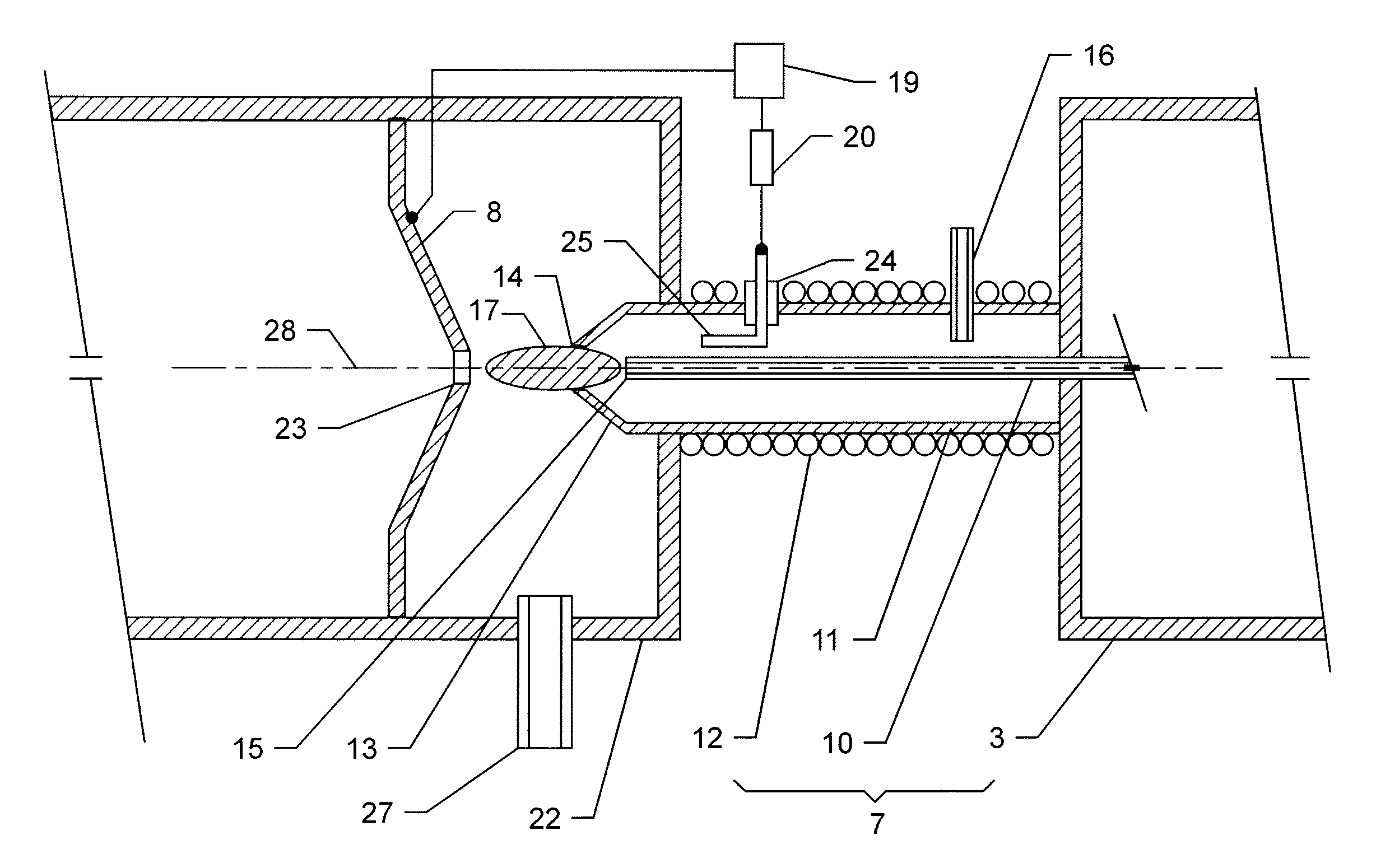
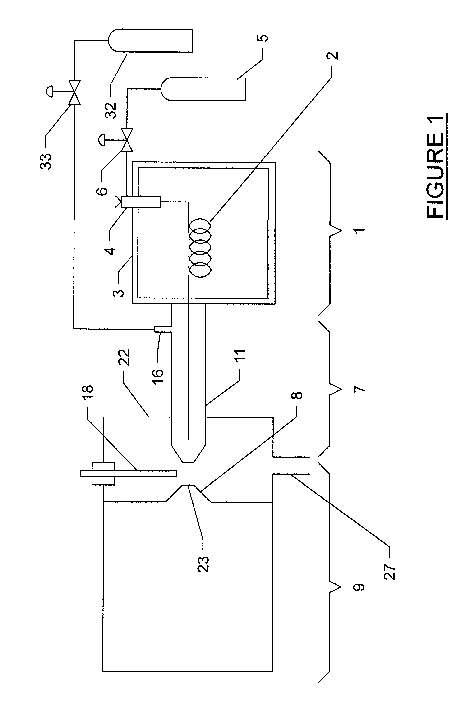
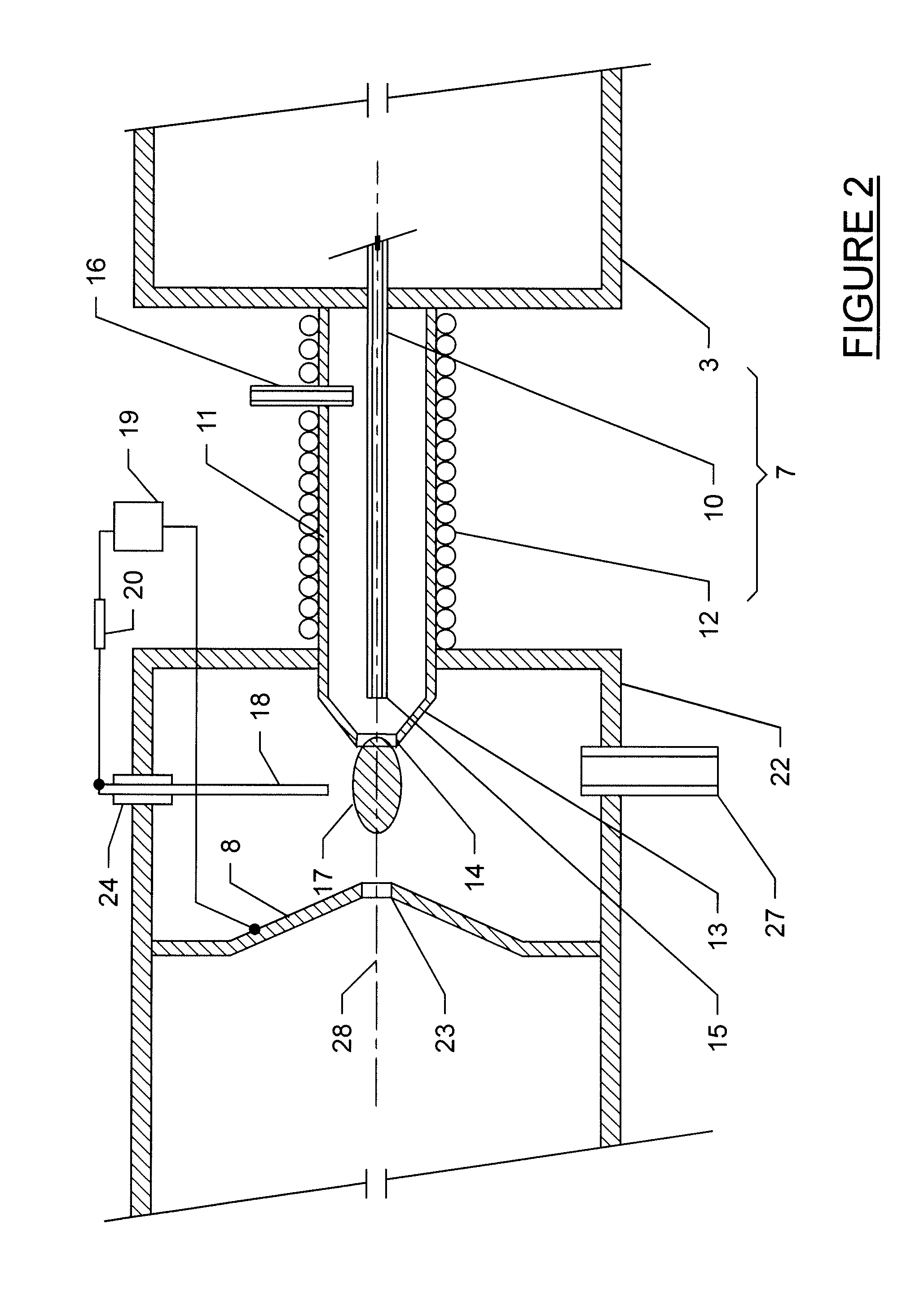
[0032]An embodiment of the invention comprising a gas chromatograph and a mass spectrometer is shown in FIG. 1. A gas chromatograph 1 comprises a capillary column 2 inside a temperature controlled oven 3. Analyte is introduced on to the column 2 through a sample injector 4 into a flow of a first gas from a reservoir 5. A flow controller 6 is provided to maintain a constant flow of the first gas, which may conveniently comprise helium. A flow of about 1 ml / minute would be suitable for many capillary GC columns. The column 2 is a coil of metal or glass capillary tubing, typically 250 μm internal diameter and 350 μm outside diameter, internally coated with a stationary phase suitable for effecting separation of different chemical components comprised in the analyte. The effluent from the column 2, comprising analyte molecules in a flow of the first gas at a pressure approximately equal to or slightly greater than atmospheric pressure, passes into an interface device generally indicated...


PUM


Abstract

The invention provides improved apparatus for, and methods of, ionizing analyte molecules in a flow of gas, typically at or around atmospheric pressure. The invention may be used to facilitate mass spectrometric analysis of analytes comprised in the effluent form a gas chromatograph. Ionization may be effected by atmospheric pressure chemical ionization or by atmospheric pressure photo ionization.

Description

CROSS REFERENCE TO RELATED APPLICATIONS[0001]This application claims benefit of U.S. Provisional Application No. 61 / 259,687, filed Nov. 10, 2009. The contents of this application is expressly incorporated herein by reference in its entirety.FIELD OF INVENTION[0002]This invention relates to apparatus and methods for mass spectrometrically analysing analyte materials comprised in a flow of gas, for example in the effluent from a gas chromatograph, typically at or slightly above atmospheric pressure.BACKGROUND[0003]Gas Chromatography—Mass Spectrometry (GCMS) is a powerful analytical technique first commercially developed in the late 1960's but which has to some extent been eclipsed by the more recent development of liquid chromatography-mass spectrometry as a routine analytical tool. Nevertheless, in view of its high sensitivity and relative ease of use, GCMS is a valuable method of analysis of compounds amenable to separation by gas chromatography.[0004]Many prior GCMS instruments emp...

Claims


Application Information

Patent Timeline
Patent Type & Authority Applications(United States)
IPC IPC(8): H01J49/26B01D59/44
CPCG01N30/7206H01J49/168H01J49/10H01J49/0422
Inventor JARRELL, JOSEPH A.
Owner WATERS TECH CORP
Why Eureka
Try Eureka