Method for Measuring a Piezoelectric Response by Means of a Scanning Probe Microscope

a scanning probe microscope and piezoelectric technology, applied in the field of piezoelectric response measurement by scanning probe microscope, can solve the problems of slow measurement, low-pass filter of lock-in, inability to measure, etc., and achieve the effect of high sensitivity

Inactive Publication Date: 2011-11-03
SPECS ZURICH
View PDF8 Cites 17 Cited by
  • Summary
  • Abstract
  • Description
  • Claims
  • Application Information

AI Technical Summary

Benefits of technology

[0010]The general object of the present invention is t

Problems solved by technology

But this is not possible due to the phase changes by 180 degrees when moving from one polarization to a reversed polarization of the sample.
The disadvantage of this techniques is that the low-pass filters of the lock-ins have to be narrow such that the two frequencies do not disturb each other.
For high Q resonances this results in

Method used


Image

  • Method for Measuring a Piezoelectric Response by Means of a Scanning Probe Microscope
  • Method for Measuring a Piezoelectric Response by Means of a Scanning Probe Microscope
  • Method for Measuring a Piezoelectric Response by Means of a Scanning Probe Microscope

Examples


embodiment 1

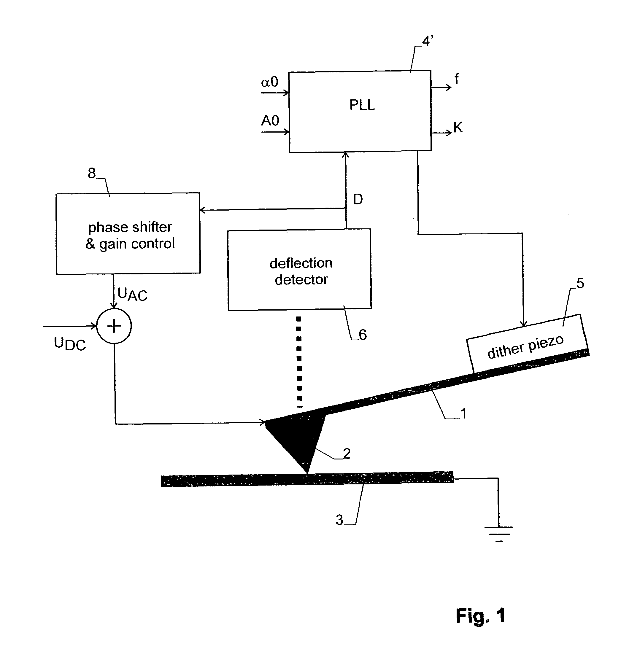
[0027]FIG. 1 shows a scanning probe microscope having a flexible cantilever 1 and a probe 2 with a fine tip, which is moved along the surface of a sample 3. Cantilever 1 is the mechanical resonator of the microscope. The tip of probe 2 is advantageously in continuous mechanical contact with the sample 3.

[0028]The scanning probe microscope is provided with suitable means for adjusting the x-, y- and z-position of probe 2 in respect to sample 3. These means, which are not shown in any of the figures, can be implemented in various manner known to the person skilled in the art.

[0029]The components shown in the figures represent the parts of the microscope that allow to measure the piezoelectric response of sample 3 by applying a voltage between probe 2 and sample 3. They comprise a phase looked loop (PLL) controller 4′ driving a dither piezo 5, which acts as an actuator applying a mechanical force to cantilever 1. (If cantilever 1 is itself of a piezoelectric material, no separate actua...

embodiment 2

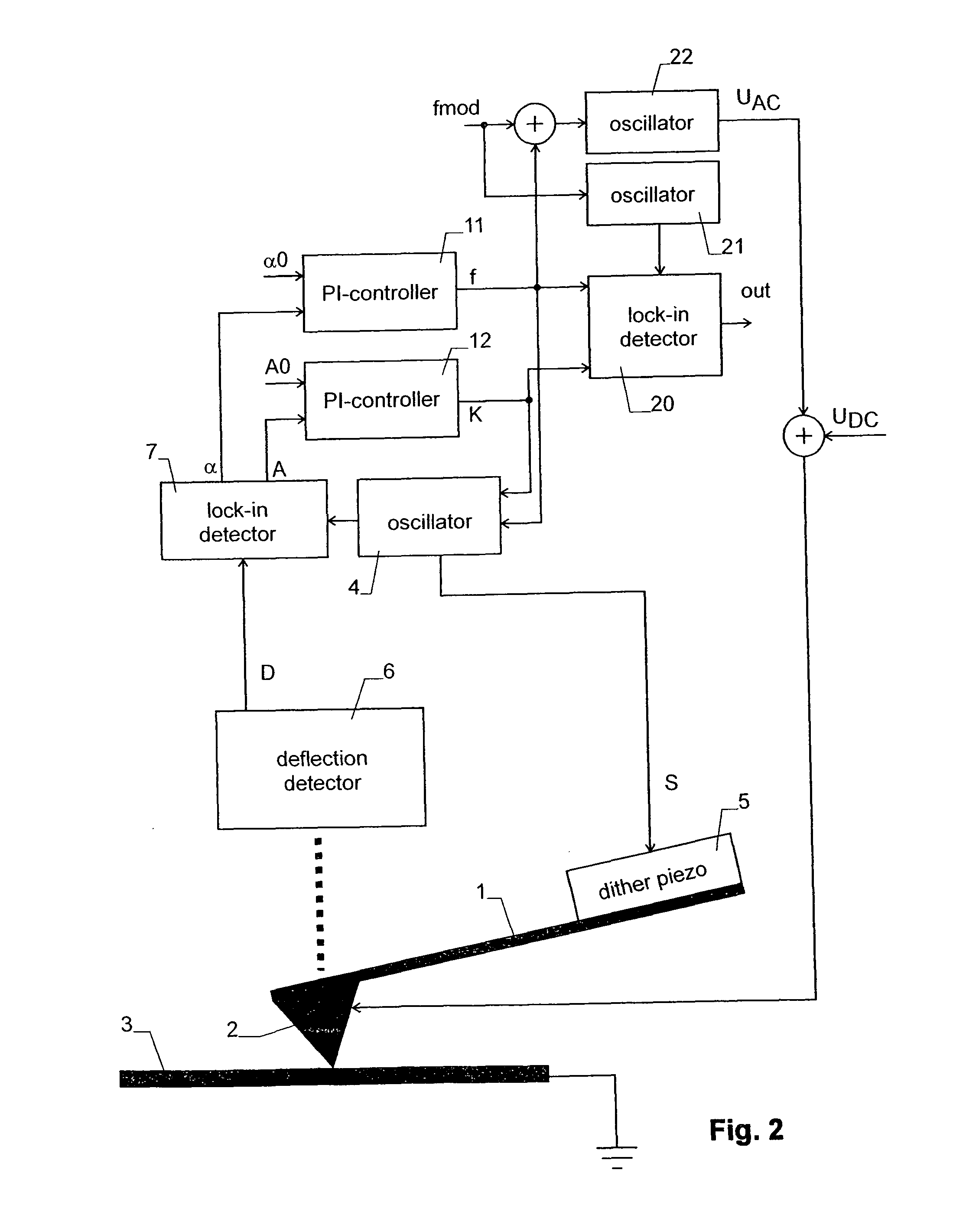
[0041]The second embodiment as shown in FIG. 2 also excites cantilever 1 on its resonance frequency f, but UAC has a different frequency fAC.

[0042]The mechanical resonator is again excited by means of a closed loop comprising a PI controller 11 generating a frequency signal f indicative of the current resonance frequency of the resonator, a PI controller 12 generating an amplitude signal K, and an oscillator generating a master signal S at frequency f with amplitude K. Master signal S drives dither piezo 5, which again acts as an actuator applying a mechanical force to cantilever 1. Since a PLL is used the frequency is chosen on the resonance.

[0043]The oscillatory deflection of cantilever 1 is measured by deflection detector 6 and a lock-in detector 7, with the latter generating signals indicative of the phase shift α of the deflection D in respect to master signal S and its amplitude A at frequency f.

[0044]PI-controller 11 compares the phase α from lock-in amplifier 7 with a phase ...

embodiment 2 — digital implementation

Embodiment 2—Digital Implementation

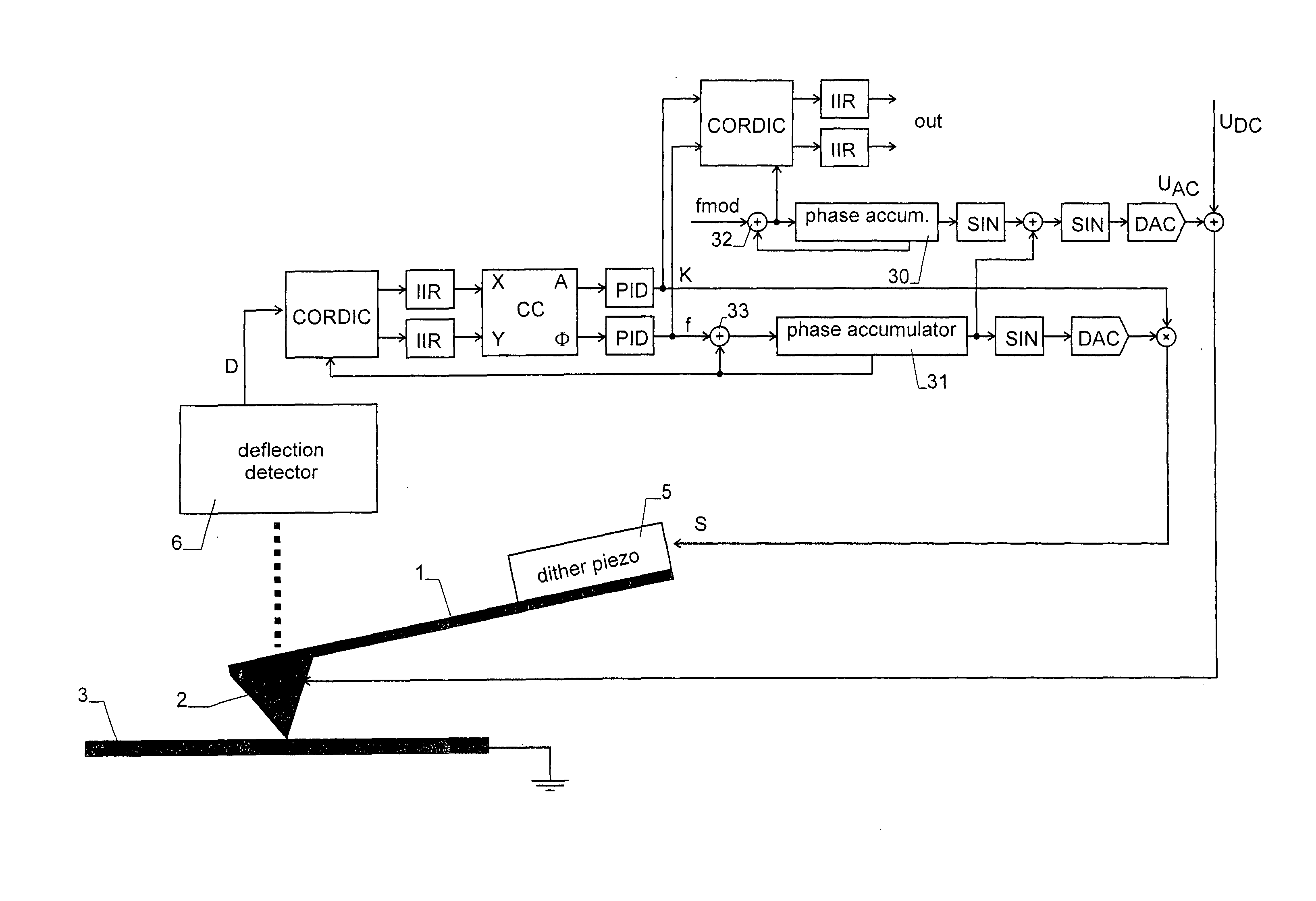
[0058]FIG. 3 shows an implementation of the embodiment of FIG. 2 as a Field Programmable Gate Array (FPGA). In the figure, the following abbreviations are used:[0059]CORDIC: Coordinate Rotation Digital Computer. Such a unit implements an algorithm that can be used for rotating a vector. It has two inputs (x, y) describing the input vector, an input phi indicating the angle of rotation, and two outputs describing the rotated vector.[0060]CC: Coordinate Converter, a unit converting Cartesian coordinates into polar coordinates. This functionality can e.g. be implemented by means of a CORDIC.[0061]PID: Proportional, Integral and Differential controller.[0062]SIN: A lookup table for sine (or cosine) values for generating a sine (or cosine) waveform from a series of consecutive integer numbers.[0063]DAC: digital analog converter.

[0064]The two phase accumulators are registers that are incremented by a given value in each cycle, the value representing the ...


PUM


Abstract

The piezoelectric response of a sample is measured by applying a scanning probe microscope, whose probe is in contact with the sample The probe is mounted to a cantilever and an actuator is driven by a feedback loop to oscillate at a resonance frequency f. An AC voltage with principally the same frequency f but with a phase (with respect to the oscillation) and/or amplitude varying periodically with a frequency fmod is applied to the probe for generating a piezoelectric response of the sample A lock-in detector measures the spectral components at the frequency fmod of the control signals (K, f) of the feedback loop. These components describe the piezoelectric response and can be recorded as output signals of the device. The method allows a reliable operation of the resonator at its resonance frequency and provides a high sensitivity.

Description

TECHNICAL FIELD[0001]The invention relates to a method for measuring a piezoelectric response of a sample by means of a scanning probe microscope.BACKGROUND ART[0002]In Piezo Response Force Microscopy (PFM) thin films of piezoelectric materials are investigated by means of a scanning probe microscope. An AC voltage is applied between the probe and the sample in order to generate an alternating electric field in the sample in order to obtain the piezoelectric response.[0003]The probing tip touches the surface with a controlled normal DC force. The oscillation of the tip due to the piezo mechanical response of the sample caused by the AC signal is detected with a lock-in amplifier and is a measure of the polarization of the piezo electric sample.[0004]This type of measurement is e.g. widely used for characterizing thin ferroelectric storage media. In particular, it can be applied to obtain a spatially resolved image of the polarization direction and the domains of the sample.[0005]In ...

Claims


Application Information

Patent Timeline
IPC IPC(8): G01Q60/00
CPCB82Y35/00G01Q60/32G01Q10/065
Inventor RYCHEN, JORG
Owner SPECS ZURICH
Why Eureka
Try Eureka